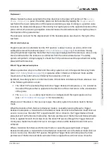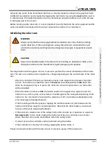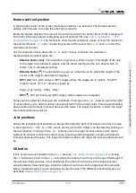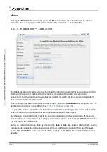
Similarly, the name of the installation file that is currently loaded is shown in the grey text field.
A different installation can be loaded by tapping the text field or by using the
Load
button next to
it. Alternatively, the loaded installation can be customized using the buttons next to the 3D view
in the lower part of the screen.
Before starting up the robot arm, it is very important to verify that both the active payload and the
active installation correspond to the actual situation the robot arm is currently in.
Initializing the robot arm
WARNING
Always verify that the actual payload and installation are correct before starting
up the robot arm. If these settings are wrong, the robot arm and control box will
not function correctly and may become dangerous to people or equipment around
them.
CAUTION
Great care should be taken if the robot arm is touching an obstacle or table, since
driving the robot arm into the obstacle might damage a joint gearbox.
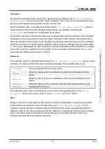
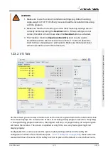
The large button with the green icon on it serves to perform the actual initialization of the robot
arm. The text on it, and the action it performs, change depending on the current state of the robot
arm.
• After the controller PC boots up, the button needs to be tapped once to power the robot
arm on. The robot arm state then turns to
Power on
and subsequently to
Idle
. Note that
when an emergency stop is in place, the robot arm cannot be powered on, so the button
will be disabled.
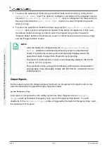
• When the robot arm state is
Idle
, the button needs to be tapped once again to start the
robot arm up. At this point, sensor data is checked against the configured mounting of the
robot arm. If a mismatch is found (with a tolerance of 30
∘
), the button is disabled and an
error message is displayed below it.
If the mounting verification passes, tapping the button releases all joint brakes and the
robot arm becomes ready for normal operation. Note that the robot makes a sound and
moves a little while releasing the brakes.
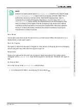
• If the robot arm violates one of the safety limits after it starts up, it operates in a special
Recovery mode
. In this mode, tapping the button switches to a recovery move screen
where the robot arm can be moved back within the safety limits.
• If a fault occurs, the controller can be restarted using the button.
• If the controller is currently not running, tapping the button starts it.
Finally, the smaller button with the red icon on it serves to power off the robot arm.
User Manual
115
UR10
C
o
p
yr
ig
h
t
©
2
0
0
9
–
2
0
2
0
b
y
U
n
iv
e
rs
a
l
R
o
b
o
ts
A
/S
.
A
ll
ri
g
h
ts
re
s
e
rv
e
d
.
Summary of Contents for UR10/CB3
Page 1: ...Universal Robots User Manual UR10 CB3 Original instructions en...
Page 28: ...UR10 20 User Manual Copyright 2009 2020 by Universal Robots A S All rights reserved...
Page 30: ...UR10 22 User Manual Copyright 2009 2020 by Universal Robots A S All rights reserved...
Page 36: ...UR10 28 User Manual Copyright 2009 2020 by Universal Robots A S All rights reserved...
Page 56: ...UR10 48 User Manual Copyright 2009 2020 by Universal Robots A S All rights reserved...
Page 62: ...UR10 54 User Manual Copyright 2009 2020 by Universal Robots A S All rights reserved...
Page 64: ...UR10 56 User Manual Copyright 2009 2020 by Universal Robots A S All rights reserved...
Page 72: ...China RoHS UR10 64 User Manual Copyright 2009 2020 by Universal Robots A S All rights reserved...
Page 73: ...KCC Safety User Manual 65 UR10 Copyright 2009 2020 by Universal Robots A S All rights reserved...
Page 92: ...UR10 84 User Manual Copyright 2009 2020 by Universal Robots A S All rights reserved...
Page 116: ...UR10 108 User Manual Copyright 2009 2020 by Universal Robots A S All rights reserved...
Page 124: ...UR10 116 User Manual Copyright 2009 2020 by Universal Robots A S All rights reserved...
Page 164: ...UR10 156 User Manual Copyright 2009 2020 by Universal Robots A S All rights reserved...
Page 214: ...UR10 206 User Manual Copyright 2009 2020 by Universal Robots A S All rights reserved...

