1.20.6. Safety Modes
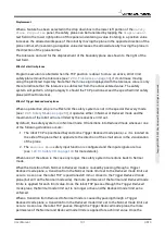
Under normal conditions (i.e. when no protective stop is in effect), the safety system operates in
one of the following
safety modes
, each with an associated set of safety limits:
Normal mode
The safety mode that is active by default;
Reduced mode
Active when the robot TCP is positioned beyond a
Trigger Reduced mode
plane (see
).
1.20.12. Boundaries on page 97
), or when triggered using a
configurable input (see
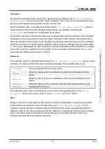
Recovery mode
When the robot arm is in violation of one of the other modes (i.e.
Normal
or
Reduced
mode)
and a Stop Category 0 has occurred,
the robot arm will start up in
Recovery
mode. This
mode allows the robot to move slowly back to the allowed area using
MoveTab
or
Freedrive
.
It is not possible to run programs for the robot in this mode.
WARNING
Note that limits for
joint position
,
TCP position
and
TCP orientation
are disabled in
Recovery
mode, so take caution when moving the robot arm back within the
limits.
The subtabs of the
Safety Configuration
screen enable the user to define separate sets of
safety limits for
Normal
and
Reduced
mode. For the tool and joints,
Reduced
mode limits
regarding speed and momentum are required to be more restrictive than their
Normal
mode
counterparts.
When a safety limit from the active limit set is violated, the robot arm performs a Stop Category
0. If an active safety limit, such as a joint position limit or a safety boundary, is violated already
when the robot arm is powered on, it starts up in
Recovery
mode. This makes it possible to move
the robot arm back within the safety limits. While in
Recovery
mode, the movement of the robot
arm is limited by a fixed limit set that is not customizable by the user. For details about
Recovery
mode limits, see the Hardware Installation Manual .
1. According to IEC 60204-1, see Glossary for more details.
1.20.7. Freedrive Mode
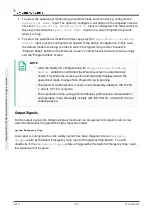
When in
Freedrive
mode (see
) and the movement of the robot arm comes
close to certain limits, the user will feel a repelling force. This force is generated for limits on
the position, orientation and speed of the robot TCP and the position and speed of the joints.
The purpose of this repelling force is to inform the user that the current position or speed is
close to a limit and to prevent the robot from violating that limit. However, if enough force is
applied by the user to the robot arm, the limit can be violated. The magnitude of the force
increases as the robot arm comes closer to the limit.
User Manual
91
UR10
C
o
p
yr
ig
h
t
©
2
0
0
9
–
2
0
2
0
b
y
U
n
iv
e
rs
a
l
R
o
b
o
ts
A
/S
.
A
ll
ri
g
h
ts
re
s
e
rv
e
d
.
Summary of Contents for UR10/CB3
Page 1: ...Universal Robots User Manual UR10 CB3 Original instructions en...
Page 28: ...UR10 20 User Manual Copyright 2009 2020 by Universal Robots A S All rights reserved...
Page 30: ...UR10 22 User Manual Copyright 2009 2020 by Universal Robots A S All rights reserved...
Page 36: ...UR10 28 User Manual Copyright 2009 2020 by Universal Robots A S All rights reserved...
Page 56: ...UR10 48 User Manual Copyright 2009 2020 by Universal Robots A S All rights reserved...
Page 62: ...UR10 54 User Manual Copyright 2009 2020 by Universal Robots A S All rights reserved...
Page 64: ...UR10 56 User Manual Copyright 2009 2020 by Universal Robots A S All rights reserved...
Page 72: ...China RoHS UR10 64 User Manual Copyright 2009 2020 by Universal Robots A S All rights reserved...
Page 73: ...KCC Safety User Manual 65 UR10 Copyright 2009 2020 by Universal Robots A S All rights reserved...
Page 92: ...UR10 84 User Manual Copyright 2009 2020 by Universal Robots A S All rights reserved...
Page 116: ...UR10 108 User Manual Copyright 2009 2020 by Universal Robots A S All rights reserved...
Page 124: ...UR10 116 User Manual Copyright 2009 2020 by Universal Robots A S All rights reserved...
Page 164: ...UR10 156 User Manual Copyright 2009 2020 by Universal Robots A S All rights reserved...
Page 214: ...UR10 206 User Manual Copyright 2009 2020 by Universal Robots A S All rights reserved...


