background image

1.5 General Warnings and Cautions

11. Collisions can release high portions of kinetic energy, which

are significantly higher at high speeds and with high pay-

loads. (Kinetic Energy =

1

2

Mass

·

Speed

2

)

12. Combining different machines might increase hazards or cre-

ate new hazards. Always make an overall risk assessment for

the complete installation. When different safety and emer-

gency stop performance levels are needed, always choose the

highest performance level. Always read and understand the

manuals for all equipment used in the installation.

13. Never modify the robot. A modification might create haz-

ards that are unforeseen by the integrator. All authorized

reassembling shall be done according to the newest version

of all relevant service manuals. UNIVERSAL ROBOTS DIS-

CLAIMS ANY LIABILITY IF THE PRODUCT IS CHANGED

OR MODIFIED IN ANY WAY.

14. If the robot is purchased with an extra module (e.g. eu-

romap67 interface) then look up that module in the respective

manual.

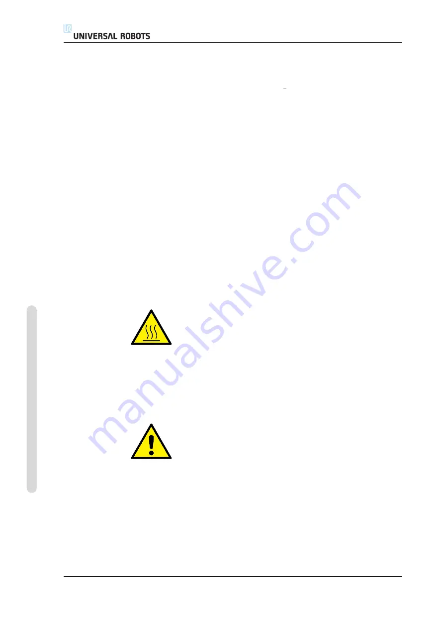
WARNING:

1. The robot and controller box generate heat during operation.

Do not handle or touch the robot while in operation or imme-

diately after operation. To cool the robot down, power off the

robot and wait one hour.

2. Never stick fingers behind the internal cover of the controller

box.

CAUTION:

1. When the robot is combined with or working with machines

capable of damaging the robot, then it is highly recom-

mended to test all functions and the robot program sepa-

rately. It is recommended to test the robot program using tem-

porary waypoints outside the workspace of other machines.

Universal Robots cannot be held responsible for any damages

caused to the robot or to other equipment due to program-

ming errors or malfunctioning of the robot.

2. Do not expose the robot to permanent magnetic fields. Very

strong magnetic fields can damage the robot.

UR5

/

CB3

I-6

Version 3.0

(rev. 15965)

Cop

yr

ight

©

2009-2014

b

y

Univ

ersal

Robots

A/S

.

All

rights

reser

v

ed.

Summary of Contents for UR5/CB3

Page 1: ...User Manual UR5 CB3 Original instructions en...

Page 2: ......

Page 3: ...User Manual UR5 CB3 Version 3 0 rev 15965 Original instructions en Serial number UR5 Serial number CB3...

Page 4: ...otice and should not be construed as a commitment by Universal Robots A S This manual is periodically reviewed and revised Universal Robots A S assumes no responsibility for any errors or omissions in...

Page 5: ...Mechanical Interface I 13 3 1 Workspace of the Robot I 13 3 2 Mounting I 13 4 Electrical Interface I 17 4 1 Introduction I 17 4 2 Electrical warnings and cautions I 17 4 3 Controller I O I 19 4 3 1 Co...

Page 6: ...e and Stopping Distance I 49 A 1 CATEGORY 0 stopping distances and times I 49 B Declarations and Certificates I 51 B 1 CE Declaration of Incorporation original I 51 B 2 Safety System Certificate I 52...

Page 7: ...12 11 Installation MODBUS client I O Setup II 27 12 12 Installation Features II 30 12 13 Installation Default Program II 34 12 13 1 Loading a Default Program II 34 12 13 2 Starting a Default Program I...

Page 8: ...Update Robot II 75 14 3 Set Password II 76 14 4 Calibrate Screen II 77 14 5 Setup Network II 77 14 6 Set Time II 78 15 Safety Configuration II 79 15 1 Changing the Safety Configuration II 80 15 2 Saf...

Page 9: ...Glossary II 97 Index II 99 Version 3 0 rev 15965 Copyright 2009 2014 by Universal Robots A S All rights reserved vii UR5 CB3...

Page 10: ...UR5 CB3 viii Version 3 0 rev 15965 Copyright 2009 2014 by Universal Robots A S All rights reserved...

Page 11: ...ng a desired trajectory What do the Boxes Contain When you order a complete robot you receive two boxes One contains the the robot arm and the following items are included in the other one Control box...

Page 12: ...ator who is expected to have a basic level of mechanical and electrical training It is also helpful though not necessary to be familiar with elementary concepts of programming No special knowledge abo...

Page 13: ...Part I Hardware Installation Manual...

Page 14: ......

Page 15: ...ance with the safety requirements set forth in the standards and regulations of the country where the robot is installed The integrators of UR robots are responsible for ensuring that the applicable s...

Page 16: ...ded could result in death or serious injury DANGER This indicates an imminently hazardous situation which if not avoided could result in death or serious injury WARNING This indicates a potentially ha...

Page 17: ...robot 5 Never use the robot if it is damaged 6 If the software prompts a fatal error immediately activate emergency stop write down the conditions that led to the er ror find the corresponding error c...

Page 18: ...is purchased with an extra module e g eu romap67 interface then look up that module in the respective manual WARNING 1 The robot and controller box generate heat during operation Do not handle or tou...

Page 19: ...eaction times of the safety functions are insufficient Use as a climbing aid Operation outside the permissible operating parameters 1 7 Risk Assessment One of the most important things that an integra...

Page 20: ...sment of the robot application shall conclude if more emergency stop buttons must be connected Emergency stop buttons should comply with IEC 60947 5 5 see more in section 4 3 2 1 9 Movement Without Dr...

Reviews: