background image

8512 

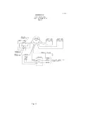
SCHEMATIC


220V, 50HZ, 1PH 

FIGURE 10 


Page 23 

Summary of Contents for Max series 8512

Page 1: ...INSTRUCTION 8512 MANUAL MAX SERIES Slicer WETHANK YOU FOR YOUR PURCHASE OF OUR MODEL 8512 SLICER 8512 498 EDS ...

Page 2: ...tions Including Disassembly Replacement and Reassembly 9 11 Replacement Parts 12 21 Warranty Information Back Cover LIST OF ILLUSTRATIONS ILLUSTRATIONS PAGE Figure 1 Overall View of Meat Slicer 2 Figure 2 Base Assembly 12 13 Figure 3 Casting and Blade Assembly 14 15 Figure 4 Arm Assembly 16 Figure 5 Slice Control Assembly 17 Figure 6 Carnage assembly 18 Figure 7 Sharpener Assembly 19 Figure 8 Elec...

Page 3: ...OR LIGHT 9 CARRIAGE ARM 2 ON OFF SWITCH 10 ELECTRIC CORD 3 FENCE 11 CARRIAGE ARM KNOB 4 KNIFE SHARPENER 12 AUTO CLUTCH LEVER 5 KNIFE GUARD 13 PROTECTIVE GUARD 6 CARRIAGE 14 GRADUATED KNOB 7 ADJUSTMENT SPACER 15 SERIAL NAME PLATE ON REAR 8 LAST SLICE DEVICE Page 2 ...

Page 4: ...termined to suit the operator It is most important that the forearm of the operator be at the proper level for ease and safety of operation as well as for maximum production This height is considered optimum when the carriage handle Figure 1 9 of the slicer is at approximately the height of the operator s elbow when standing IMPORTANT Warning Caution Electrical wiring instructions are found in the...

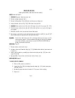
Page 5: ...s fully tightened Failure to do this could result in the carriage striking and damaging the knife edge PROTECTIVE GUARD WARNING The protective guard Figure 1 13 covers the knife edge completely except under the sharpener cover and the forward edge where slicing will be performed This forward edge is covered by the edge of the fence but only when the slice adjustment is completely closed The knife ...

Page 6: ...iece of stiff paper 8 Turn slicer ON Lightly press deburring honing button on thefrontsideofbladeand hold for 1 to 2 seconds while you turn OFF the slicer Blade should now be completely sharpened and honed Caution It is important for best slicing results not to deburr the knife too long or the keen edge will be destroyed due to the formation of an undesirable second bevel on the opposite side This...

Page 7: ... soap It is recommended that the cloth be folded over a thin wooden stick as a further caution to avoid accidental contact with the knife CAREFULLY wash between the knife edge and protective guard using a soft cloth inserted between knife edge and guard on both front and rear of knife using extreme caution to never touch the knife edge Rinse with warm water applied with a cloth Dry thoroughly with...

Page 8: ...12 LUBRICATION INSTRUCTIONS A Clean and apply mineral oil weekly C 140 WT USDA oil Change when changing gears B Apply Petro Gel 4400408 oftenas required to maintain light film D Lubricated for life Page7 ...

Page 9: ...cting rod support jammed 3 1 Adjust belt tension or replace belt 3 2 Adjust spring bushing 3 3 Check for foreign objects in mechanism 4 Excessive noise 4 1 Blade contacting knife guard 4 2 Deflector contacting blade 4 3 Sharpener contacting blade 4 4 Connecting rod support hitting bottom cover 4 5 Fan hitting motor cover 4 6 Damaged belt hitting against motor cover 4 7 Reduction gearbox 4 1 Check ...

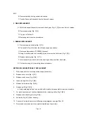
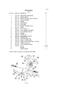
Page 10: ...vel to the slicer WARNING Worn knife should be disposed of in a safe responsible way showing concern for others who may handle it It recommended that the edge of the knife be wrapped several times with heavy tape and that a caution CAUTION SHARP EDGE be written on both sides of the knife KMFE SEAL Figure 3 1 Remove knife per above instructions 2 Unscrew and remove tapered bushing Fig 3 12 Maintain...

Page 11: ... 3 11 F Invert assembly on bench and drive bearings and spacer from back side G Put new bearing in by reversing above procedure MOTOR REPLACEMENT OR BELT REPLACEMENT 1 Follow procedure for removing blade support assembly 2 Remove acorn nuts Fig 2 47 3 Remove motor cover Fig 2 45 4 Loosen and pull fan Fig 2 48 5 Remove belt retainer Fig 2 43 6 Remove belt Fig 2 50 a If only replacing belt put on ne...

Page 12: ...emoving two bolts Fig 2 38 and removing set screw at reduction gear end 7 Remove switch shaft Fig 8 16 by loosening nut Fig 8 15 near switch end 8 Remove capacitor on left to access ground screw holding electrical equipment casing 9 Remove electrical equipment casing by removing three screws Fig 8 21 10 Replace capacitors Fig 8 24 if found to be defective 11 Relay Fig 8 7 and switch Fig 8 20 can a...

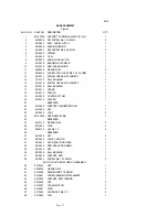
Page 13: ...8512813 SPACER 1 19 8512853 COVER BOTTOM 1 20 8512816 SPACER 1 21 RESERVED 22 8512805 SUPPORT CONNECTION ROD 1 23 8512808 KEY 1 24 8512855 FOOT 4 25 8512803A GEAR REDUCTION 1 26 RESERVED 27 8512516 WASHER M6 4 28 8512803 STUD 4 29 6509143 NUT M6 1 0 4 30 RESERVED 31 8512846 KEY 4 32 8512845 PULLEY MOTOR 1 33 8512831 KEY REDUCTION GEAR 1 34 8512830 ROD REDUCTION GEAR 1 35 8512836 KEY 1 36 8512834 B...

Page 14: ...re 2 CONT ILLUS NO PART NO DESCRIPTION QTY 49 8512835 PULLEY For 115V 100V 1 8512835A PULLEY For 220V 1 50 8512837 V BELT For 115V 100V 1 8512837A V BELT For 220V 1 51 8512637 VENT PLASTIC 1 52 8512248 LEG EXTENSION 4 Page 13 ...

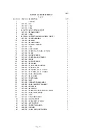
Page 15: ...RAPER 1 19 8512234 FENCE 1 20 8512236 SUPPORT FENCE 1 21 8512237 SET SCREW 1 22 6509080 STUD FENCE ADJUSTING 2 23 6509081 ACORN NUT M8 2 24 6509098 SET SCREW M6 1 0 X 10MM 1 25 8512214 SET SCREW M6 1 0 X 16MMB 1 26 7510084 KNOB GRADUATED 1 27 8512211 REAR WHEEL 1 28 8512210 FRONT WHEEL 1 29 8512209 RIVET 2 30 8512208 GRADUATED KNOB BUSH 1 31 6509024 KNOB GUARD ATTACHMENT 1 32 8512206 DOWEL PIN 1 3...

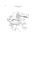
Page 16: ...8512 CASTING and BLADE ASSEMBLY Figure 3 Page 15 ...

Page 17: ...17 SCREW 2 10 6509033 NUT JAM M10 1 5 1 11 6509032 STUD BUSHING ADJUSTMENT 1 12 8512308 BOLT BEARING LOCKING 1 13 6509031 BEARING 1 14 6509028 WASHER M8 1 15 6509042 STUD ARM ATTACHMENT 1 16 8512319 CARRIAGE ARM 1 17 6509044 KNOB CARRIAGE ARM 1 18 6509045 HANDLE CARRIAGE ARM 1 19 6509046 SCREW HEX HD WASHER M6 1 0 X 15MM 2 20 8512325 CARRIAGE ANCHOR 1 21 8512326 STUD CARRIAGE ANCHOR 1 22 1200377 O...

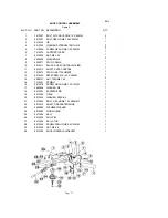
Page 18: ...12512 SHAFT SLICE CONTROL 1 12 7510073 STUD JIB ATTACHMENT 1 13 8512326 SET SCREW M8 1 25 X 20MM 1 14 6509131 NUT THIN M8 1 25 2 15 7510061 SPRING 1 16 8512518 SCREW HEX HD M6 1 0 X 10MM 1 17 6509046 WASHER M6 1 18 8512501 ECCENTRIC PIN 1 19 8512502 GEAR 1 20 8512503 WASHER SPECIAL 1 21 8512504 BOLT HEX HD M8 1 25 X 50MMT 1 22 8512510 SHAFT GRADUATED KNOB 1 23 6509086 FLEXIBLE WASHER 1 24 8512507 ...

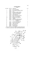
Page 19: ... SLICE DEVICE SHAFT 3 9 8512428 SHAFT LAST SLICE DEVICE 1 10 8512427 BUSHING LAST SLICE DEVICE 1 11 8512425 CARRIAGE 1 12 8512438 NYLON PIP ADJUSTMENT SPACER 1 13 8512434 SHAFT ADJUSTMENT SPACER 1 14 RESERVED 15 8512431 NYLON PIP LAST SLICE DEVICE 8 16 8512927 STUD LAST SLICE DEVICE 1 17 6509038 SCREW FLAT HEAD 1 18 6509058 BOX NUT M10 1 5 1 19 6509059 WASHER SPECIAL 1 20 8512439 STUD CARRIAGE 1 P...

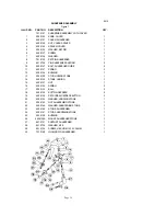
Page 20: ...9127 SPRING 2 12 6509128 BUSHING 1 13 6509129 STUD HONING STONE 1 14 6509130 STONE HONING 1 15 6509131 NUT 1 16 6509134 SPRING 2 17 6509133 BALL 2 18 6509135 BUTTON DEPRESS 2 19 6509136 SET SCREW DEPRESS BUTTON 2 20 6509132 WASHER HORNING STONE 1 21 6509143 NUT SHARPENING STONE 1 22 6509144 WASHER SHARPENING STONE 1 23 6509142 STONE SHAR PENING 1 24 6509141 STUD SHARPENING STONE 1 25 6509128 BUSHI...

Page 21: ... MOTOR SHORT 1 11 1814069 LAMP WARNING 115V 100V 1 1814069A LAMP WARNING 220V 1 12 8512624 FASTENER CABLE 1 13 8512627 SCREW PHIL HD SHEET METAL 3 14 8512615 KNOB SWITCH 1 15 8512614 NUT M6 10 2 16 8512613 SHAFT SWITCH 1 17 4400053 CORD AND PLUG 115V 100V 1 4400053A CORD AND PLUG 220V 1 18 8512612 JOINT 1 19 8512611 NUT 1 20 7120009 SWITCH 1 21 8512609 SCREW M5 0 8 X 12MM 3 22 8512626 COVER CASING...

Page 22: ...8512 ELECTRICAL ASSEMBLY Figure 8 Page 21 ...

Page 23: ...8512 SCHEMATIC 115V 60HZ 1PH 100V 50 60HZ 1PH Figure 9 Page 22 ...

Page 24: ...8512 SCHEMATIC 220V 50HZ 1PH FIGURE 10 Page 23 ...

Reviews: