3
d.
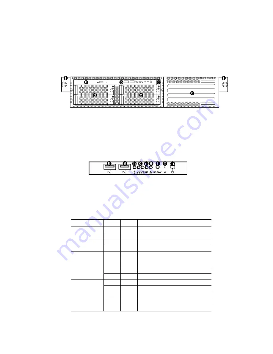
Hard Disk Drive
e.
Front Bezel
f.
Mounting Bracket
a.
Slim CD-ROM Drive
b.
Front Panel Controls and
Indicators
c.
FDD Ejector button
1.1 System Feature
1.1.1 Front View
1.1.2 Front Panel Controls and Indicators
Front Side LEDs
LED Color
State
Description
Blue
On
System is turned on
System Power
Off
Off
Power is off
Green
Blink
Network is linked and accessed
LAN1/LAN2 Activity
Green
Off
No LAN access
White On
Identification is active by management software
or ID LED button
System ID
Off
Off
Identification is not active
Off Off
Running/normal
operation
System Fault
Red
On
Critical or non-recoverable condition
Green
On
HDD exists and is powered
HDD Status
Off
Off No
HDD
Green Blink Disk
is
accessed
Red
Blink
Disk has problem or on Rebuilding
HDD Activity/Fail
Off
Off
No disk activity
a.
USB 2,0 Ports
b.
Power LED
c.
LAN Activity LED
d.
System ID LED
e.
System Fault LED
f.
System ID Switch
g.
Reset Switch
h.
Power ON/OFF Switch
Summary of Contents for XtremeServer 2544
Page 1: ......
Page 12: ...9 1 3 Mainboard Layout 1 3 1 Block Diagram ...
Page 26: ...23 ...
Page 43: ...40 4 1 6 PCI PnP Menu PCI PnP Menu 1 PCI PnP Menu 2 ...
Page 46: ...43 4 1 8 Security Menu Security Menu 1 Change Supervisor Security Menu 2 Change User ...
Page 48: ...45 4 1 9 Chipset Configuration Menu 4 1 9 1 NorthBridge Chipset Configuration Submenu ...


