74
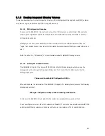
5.1.5 Creating Integrated Striping Volumes
This section describes how to create Integrated Striping (IS) volumes using the LSI Logic SAS BIOS Configuration
Utility (SAS BIOS CU).
5.1.5.1 Configuration Overview
You can use the SAS BIOS CU to create multiple IS volumes, with up to 10 drives total on an LSI Logic SAS
controller. Each volume can have from 2 to 8 drives. Disks in an IS volume must be connected to the same
LSI Logic SAS controller, and the controller must be in the BIOS boot order.
Although you can use disks of different size in IS volumes, the smallest disk determines the “logical” size of
each disk in the volume. In other words, the excess space of the larger member disk is not used. Usable
disk space for each disk in an IS volume is adjusted down to leave room for metadata. Usable disk space
may be further reduced to maximize the ability to interchange disks in the same size classification. The
supported stripe size is 64 Kbytes.
Refer to Section 4.2, “IS Features,” for more information about Integrated Striping volumes.
5.1.5.2 Creating IS Volumes
The SAS BIOS CU is part of the Fusion-MPT BIOS. When the BIOS loads during boot and you see the
message about the Setup Utility, press Ctrl-C to start it. After you do this, the message changes to:
Please wait, invoking SAS Configuration Utility...
After a brief pause, the main menu of the SAS BIOS CU appears. On some systems, however, the following
message appears next:
LSI Logic Configuration Utility will load following initialization!
In this case, the SAS BIOS CU will load after the system has completed its power-on self test.
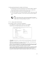
Follow the steps below to configure an Integrated Striping (IS) volume with the SAS BIOS CU. The
procedure assumes that the required controller(s) and disks are already installed in the computer system.
You can configure both IM and IS volumes on the same SAS controller.
①
On the Adapter List screen of the SAS BIOS CU, use the arrow keys to select a SAS adapter.
②
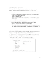
Press Enter to go to the Adapter Properties screen, shown in Figure.
Summary of Contents for XtremeServer 2544
Page 1: ......
Page 12: ...9 1 3 Mainboard Layout 1 3 1 Block Diagram ...
Page 26: ...23 ...
Page 43: ...40 4 1 6 PCI PnP Menu PCI PnP Menu 1 PCI PnP Menu 2 ...
Page 46: ...43 4 1 8 Security Menu Security Menu 1 Change Supervisor Security Menu 2 Change User ...
Page 48: ...45 4 1 9 Chipset Configuration Menu 4 1 9 1 NorthBridge Chipset Configuration Submenu ...

