Scales - Models 410 and 520
— Set Up
2-36
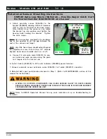
PROXIMITY
SENSOR
(9006076)
ALLOW CLEARANCE FOR
SCREW ON HOSE CLAMP
PIVOT BRACKET DOWN INTO
POSITION AND SECURE IN PLACE
FIG. 2-34
FIG. 2-35
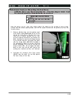
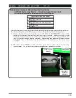
Rotational Sensor Mounting Instructions
(continued)
UM520 Auto-Log Scale — Double-Auger Grain Cart
For Serial Number B34930100 and Higher
4. Attach proximity sensor (9006076) to bracket,
allowing sufficient clearance (1/8” to 1/4”) for
the screw on the hose clamp, see figure 2-34.
Pivot the bracket down and secure in place
with opposite lower bearing bolt, see figure
2-35. Tighten hardware.
NOTE: Use two washers provided in the hardware
box or two quarters to set the gap between the
end of the sensor and hose clamp.
NOTE: If more than 1/2” of hose clamp band
extends beyond the adjustment screw, cut ex
-
cess off.
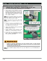
5. Connect 16’ extension cable (9006131) to sen
-
sor cable and route securely along the grain
cart tongue into the tractor cab.
6. Install Y-cable (9006132) to 520 scale indicator
(9005980) power terminal.
7. Connect proximity sensor extension cable
(9006076) to Y-cable (9006132) connector.
8. Reinstall belt cover and driveline removed in
Step 1. (Refer to MAINTENANCE section of
this manual for instructions.)
•
MOVING OR ROTATING COMPONENTS CAN CAUSE SERIOUS INJURY OR DEATH ENSURE
SERVICE COVERS, CHAIN/BELT COVERS AND CLEAN-OUT DOOR ARE IN PLACE AND SECURELY
FASTENED BEFORE OPERATING UNIT.
NOTE: Refer to UM520 Operator’s Manual for any scale indicator set up or troubleshooting in
-
formation.


