background image

Scales - Models 410 and 520


— Operation & Maintenance

3-16


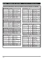
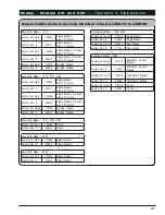
Scale “Short Form” Set Up & Calibration 

(continued)

Unverferth 520 Indicator

To  change  SETUP  number:
Enter  D.A.N.  code  871,  press  SELECT,  current  SETUP  number  will  display.  Enter  the  new  SETUP 
number  and  press  ENTER.

To  change  CAL    number:
Enter  D.A.N.  code  872,  press  SELECT,  current  CAL  number  will  display.  Enter  the  new  CAL  num

-

ber  and  press  ENTER.

NOTE:  Refer  to  UM410  or  UM520  Operator’s  manual  for  any  indicator  set  up  or  troubleshooting 

information.

Summary of Contents for UM410

Page 1: ...Grain Handling Digi Star Scales Installation and Parts Models UM410 UM520 Scale Serial 40000 and Higher Part No 266900 ...

Page 2: ...l are for your protection Read them care fully and follow them closely when working around or using this machine Read and study this manual completely before attempting to operate this implement Take this manual to the field for handy reference when operating adjusting or servicing your machine When referenced Right Hand RH and Left Hand LH side of the machine are determined by standing behind the...

Page 3: ...rranty questions Please fill out and retain this portion for your records Purchase Date _____________Model _________________Serial No _______________________________ Dealer ____________________________________ City ____________________________________________ Dealer Contact _______________________________ Phone ______________________________________ The information specifications and illustrations...

Page 4: ...e Indicator Installation All Models 2 5 3 Point Scales with Spindles 2 6 Hitch Assembly 2 6 Axle Load Cell Installation 2 8 3 Point Scales wtih Compression Cells 2 9 Hitch Assembly 2 9 Axle Load Cell Installation 2 10 Axle Load Cell and Riser Installation 2 12 5 Point Scales Tandems 2 14 Hitch Assembly 2 17 Axle Load Cell Installation 2 18 5 Point Scales Tracks 2 19 Layout for Models with Track 2 ...

Page 5: ...5 835 1035 1135 Parker Models 742 842 1042 1142 Double Auger Grain Carts Models 1110 1310 1196 1396 1596 2096 Serial Number B34930099 and Lower 2 33 Models All Double Auger Grain Carts Serial Number B34930100 and Higher 2 35 Section III Operation Maintenance Wheel Hub and Spindle Disassembly and Assembly 3 2 Scale Calibration and Set Up Number Charts UM410 UM520 3 4 Scale Calibration and Set Up UM...

Page 6: ...PACKAGE PARTS 3 Point Scales Spindles 4 6 Single Tires with 3 Point Scales Compression Cells 4 14 Walking Tandem Steerable Tandems In Line Tandems 5 Point Scales 4 18 Tracks with 5 Point Scales 4 22 Single Tires 5 Point Scales 4 28 Rotational Sensor Mounting Kit For UM520 Scale 4 32 ...

Page 7: ... 520 Safety 1 1 Section I Safety General Hazard Information 1 2 Following Safety Instructions 1 3 Before Servicing 1 3 Before Operating 1 3 During Operation 1 4 Preparing for Emergencies 1 4 Wearing Protective Equipment 1 4 ...

Page 8: ... will be done by the operators who accept the full measure of their responsibility It is true that the designer the manufacturer and the safety engineer can help and they will help but their combined efforts can be wiped out by a single careless act of the operator It is said that the best kind of a safety device is a careful operator We at Unverferth Mfg Co Inc ask that you be that kind of operat...

Page 9: ...ing grain traps and suffocates victims in seconds Before Servicing Avoid working under an implement however if it becomes absolutely unavoidable make sure the implement is safely blocked To prevent personal injury or death always ensure that there are people who remain outside the cart to assist the person working inside and that all safe workplace practices are fol lowed There is restricted mobil...

Page 10: ...r on hillsides Do not leave towing vehicle and implement unattended with engine running Preparing for Emergencies Keep a first aid kit and properly rated fire extinguisher nearby Keep emergency numbers for fire rescue and poison control personnel near the phone Wearing Protective Equipment Wear clothing and personal protective equipment appropriate for the job Wear steel toed shoes when operating ...

Page 11: ...oint Scales wtih Compression Cells 2 9 Hitch Assembly 2 9 Axle Load Cell Installation 2 10 Axle Load Cell and Riser Installation 2 12 5 Point Scales Tandems 2 14 Hitch Assembly 2 17 Axle Load Cell Installation 2 18 5 Point Scales Tracks 2 19 Layout for Models with Track 2 19 Hitch Assembly 2 20 Axle Load Cell Installation 2 21 5 Point Single Tires 2 22 Hitch Assembly 2 23 Axle Load Cell Installati...

Page 12: ...782 882 1082 1182 1186 1282 1386 V700 V800 V1000 V1100 V1300 V1500 Unverferth Models 760 860 1015 1017 1019 1050 1060 1115 1117 1119 1160 1315 1317 1319 1519 7250 8250 9250 Killbros Models 735 835 1035 1135 Parker Models 742 842 1042 1142 Double Auger Grain Carts Models 1110 1310 1196 1396 1596 2096 Serial Number B34930099 and Lower 2 33 Models All Double Auger Grain Carts Serial Number B34930100 ...

Page 13: ...D THESE ASSEMBLY INSTRUCTIONS WILL REQUIRE A SAFE LIFTING DEVICE PER MODEL AS LISTED IN THE FOLLOWING CHARTS SPECIFIC LOAD RATINGS FOR INDIVIDUAL LOADS WILL BE GIVEN AT THE APPROPRIATE TIME IN THE INSTRUCTIONS EYE PROTECTION AND OTHER APPROPRIATE PERSONAL PROTECTIVE EQUIPMENT MUST BE WORN WHILE SERVICING IMPLEMENT KEEP HANDS CLEAR OF PINCH POINT AREAS Park the empty grain cart on a firm level surf...

Page 14: ...ll Models 1 Attach the J Block to the left vertical face of the cart using the 8 hardware NOTE Facing the J Block to the inside of the cart will protect the scale wire ends 2 Attach the cable wire connector ends to the J Block NOTE J Block has no particular connection port for a particular scale bar Scale Kit Installation ...

Page 15: ... Kit Installation Scale Indicator Installation All Models 1 Using the bracket provided locate the scale indicator inside the tractor cab NOTE For additional mounting flexibility optional RAM mount kit 9005936 is available 5 1 4 REF 2 31 32 REF ...

Page 16: ...B Hitch Assembly 1 Remove the capscrew lock washer and nut to remove the standard hitch Remove the original bushing 2 Replace with scale hitch bar making sure to feed the scale wire through the conduit to the J Block NOTE The bending direction decal on the end of the bar should point up Also the hitch bar should be installed with the serial number decal facing up ...

Page 17: ... Tires Replace Standard Hitch with Scale Hitch Weigh Bar 3 3 4 Dia 9004913 1115 1310 1315 with Single Wheel Tires Serial Number B31290099 Lower Replace Standard Hitch with Scale Hitch Weigh Bar 3 3 4 Dia 9004913 1110 with Tracks Serial Number B31290099 Lower Replace Standard Hitch with Scale Hitch Weigh Bar 3 3 4 Dia 9004913 Killbros Models 735 835 w Single Dual Wheel Tires Replace Standard Hitch ...

Page 18: ...o spindle Install outer bearing spindle washer and castle nut 5 Attach the wheel s and tire s to the hub using the same rated lifting device for removal Tighten wheel nuts to appropriate requirements and recheck as outlined in the Wheel and Tire section of this manual Raise cart remove safe lifting device and lower tire to the ground 6 Repeat steps 2 through 5 on right side of the cart SAFE LIFTIN...

Page 19: ...ing direction decal on the end of the bar pointing up with the serial number decal facing up FIG 2 2 Brent Models 782 with Single Dual Wheel Tires Serial Number B26270099 Lower Replace Standard Hitch with Scale Hitch Weigh Bar 2 7 8 Dia 9004903 782 with Single Dual Wheel Tires Serial Number B26270100 Higher Replace Standard Hitch with Scale Hitch Weigh Bar 3 3 4 Dia 9004910 780 880 1080 with Singl...

Page 20: ...time Follow Steps 2 8 before loosening hardware on any of the other bars 2 Remove cotter pins and axle retainer link pins 3 Place 5 6 or 7 ton supports under main frame rails as close to axle as possible 4 Raise cart allowing at least 2 3 between tires and floor NOTE Carts with 24 5 tires or tracks may require spacer bars to level the cart order two spacers 283856 See Axle Load Cell and Riser Inst...

Page 21: ...he flat areas of the load cell to engage Bracket plate is correctly seated when plate is approx 1 8 or less from load cell outer sleeve See figure 2 7 6 Orient compression cells so that the lead cables face rear of cart Raise axle and check to assure load cells and anti rotate brackets are aligned and that the cart load is present on compression cells See figure 2 6 Anti Rotate brackets will limit...

Page 22: ...d axle retainer link pins see figure 2 8 3 Place 4 ton supports under main frame rails as close to axle as possible 4 Raise cart allowing at least 2 3 between tires and floor NOTE Carts with tracks also use spacer bars NOTE A 1 16 shim 280396 may be necessary for scale accuracy to insure cart contacts both compression load cells simultaneously 5 Lower axle slightly remove two spacer bars and disca...

Page 23: ...ti rotate brackets and spacer bars are aligned and that the cart load is present on compression cells If the cart load is present on one cell and not on the other cell then a shim must be added to the looser cell Locate shim between the spacer bar and axle to equalize the cell loading See figure 2 13 8 Remove cart supports and lower cart to ground 9 Insert axle retainer pins and cotter pins Adjust...

Page 24: ...Point Scales Walking Tandem Serial Number Decal Facing UP Existing Hub and Wheel Use Existing Hardware If spindle has 2 holes use mounting hole closest to the hub FIG 2 14 FIG 2 15 Position With Decal On Top Bending Direction Arrow Pointing Up Walking Tandem Shown ...

Page 25: ...op Use Existing Hardware Use Existing Hardware Position With Decal On Top Hitch Casting Pin Retaining Rings Scale Kit Installation 5 Point Scales Steerable Tandems Position With Decal On Top Bending Direction Arrow Pointing Up FIG 2 16 Steerable Tandem Shown ...

Page 26: ...Scales Models 410 and 520 Set Up 2 16 Scale Kit Installation 5 Point Scales In Line Tandems Position With Decal On Bottom Bending Direction Arrow Pointing Down FIG 2 16 In Line Tandem Shown CAT 5 CAT 4 ...

Page 27: ... Models 1594 1596 with Steerable Tandem Replace Standard Hitch with Scale Hitch Weigh Bar 3 3 4 Dia 9004910 2096 with Steerable Tandem Replace Standard Hitch with Scale Hitch Weigh Bar 3 3 4 Dia 9004913 Indicator 410 9008135 Indicator 520 1194 1196 1282 1394 1396 with Walking Tandem Replace Standard Hitch with Scale Hitch Weigh Bar 3 3 4 Dia 9004910 Unverferth Models 860 1015 1050 1060 1110 1115 1...

Page 28: ...pins retaining both ends of the non scale bars 5 Replace non scale bars with scale bars using snap rings and pins removed in step 3 to connect scale bar to axle and axle mount weldments 6 Reattach capscrews flat washers lock washers and hex nuts removed in step 2 to connect the axle mount weldments to the cart frame 7 Route scale wires along axle and cart frame to location of J Block installation ...

Page 29: ...9394 020 91192 Axle Scale Bar Axle Mount Serial Number Decal Faces Down on Scale Bar 282876 91192 Bending direction arrow pointing UP Serial Number decal facing UP Model 1082 Shown All Models Except Model 1082 Layout for Models with Tracks FIG 2 17 Bending direction arrow pointing DOWN Serial Number decal facing DOWN ...

Page 30: ...n and snap rings Scale Kit Installation 5 Point Scales continued Tracks Brent Models 1082 1182 1186 1194 1196 1282 1386 1394 1396 1594 1596 2096 V800 V1000 V1100 V1300 V1500 with Tracks Replace Standard Hitch with Scale Hitch Weigh Bar 3 3 4 Dia 9004910 Unverferth Models 860 1015 1017 1019 1050 1060 1110 1115 1117 1119 1160 1310 1315 1317 1319 1519 1610 1120 1320 1620 2020 with Tracks Replace Stan...

Page 31: ...ins removed in step 3 to connect scale bar to axle and axle mount weldments NOTE Make sure serial number decal on scale bar is facing down when installed 5 Reattach capscrews flat washers lock washers and hex nuts removed in step 2 to connect the axle mount weldments to the cart frame 6 Route scale wires along axle and cart frame to location of J Block installation Scale Kit Installation 5 Point S...

Page 32: ... 2 22 Scale Kit Installation 5 Point Scales continued Single Tires Bending direction arrow pointing DOWN Serial Number decal facing DOWN FIG 2 18 Bending direction arrow pointing UP Serial Number decal facing UP USE EXISTING HARDWARE ...

Page 33: ... assemble the scale hitch bar to the tongue 5 Reattach the hitch casting to the scale hitch bar using hitch pin and snap rings Brent Models 1182 1186 1196 1282 1386 1396 V1000 V1100 V1300 Replace Standard Hitch with Scale Hitch Weigh Bar 3 3 4 Dia 9004910 Unverferth Models 760 860 1015 1017 1019 1050 1060 1110 1115 1117 1119 1120 1320 1160 1310 1315 1317 1319 1519 Replace Standard Hitch with Scale...

Page 34: ... bar should point down Also the hitch bar should be installed with the serial number decal facing down 5 Reattach capscrews and locknuts removed in step 2 to connect the axle mount weldments to the cart frame 6 Repeat steps 2 through 6 on the rear axle bar 7 Route and secure scale wires along axle and cart frame to location of J Block installation NOTE Because of movement in the grain cart s suspe...

Page 35: ...ire to GROUND The indicator is fused internally at 2 amps NOTE Only red and black wires in the power cable are used Any other wires are not used and should be capped off Disconnect the indicator power cord before jump starting or fast charging a battery Discon nect all indicator leads before welding on equipment Damage may occur to the indicator and load cells Power Cable Connections Scale Bottom ...

Page 36: ...NOTE If connecting to load cells other than those that were provided with your unit the indica tor must be calibrated Contact your dealer for assistance J Block Model To connect the load cells plug the J Block cable to the LOAD CELL connector into the bottom panel of the scale Plug the load cell cables into any port on the J Block as shown below NOTE Since J Block has parallel connections cables c...

Page 37: ...or illustration purposes only Route cables through the top of the walking tandem as shown Routing Scale Cables Models with Walking Tandems 1 Route the spindle cables through the walking tandem frame as shown in figure 2 19 and figure 2 20 FIG 2 19 FIG 2 20 ...

Page 38: ...cale Cables continued Models with Walking Tandems 2 Secure the cables to the top of the walking tandem using the bracket 268675G or 268675R 3 Route cables down the walking tandem and secure using bracket 268674G or 268674R FIG 2 21 FIG 2 22 FIG 2 23 ...

Page 39: ...he tabs on the frame with cable ties 5 Route the right hand spindle cables from the walking tandem frame along the frame as shown in figure 2 25 and secure using cable ties 6 Connect the spindle cables to the J Block and label the ports as shown in figure 2 26 Cables can be connected to any port FIG 2 24 FIG 2 25 FIG 2 26 ...

Page 40: ...3 Reusing the hex nuts and lock washers re moved in step 1 attach the brackets 252198B and 252199B NOTE Install sensor mounting brackets 252198B and 252199B with notches towards bearing to avoid interference with bearing NOTE It may be necessary to shim brackets 252198B and 252199B to avoid interference with bearing If so use provided washers to shim FIG 2 27 FIG 2 28 SINGLE AUGER GRAIN CART MODEL...

Page 41: ...t the gap between the end of the sensor and hose clamp adjusting screw NOTE Very little hose clamp should extend beyond the adjustment screw If more than 1 2 extends beyond bend down towards shaft or cut off 7 Connect 16 extension cable 9006131 to sen sor cable 9006076 and route securely along the grain cart tongue into the tractor cab 8 Install Y cable 9006132 to 520 scale indicator 9005981 power...

Page 42: ...to Log Scale Single Auger Grain Cart EZ MATE J BLOCK 9004925 UM520 SCALE INDICATOR 9005981 TO POWER SOURCE AUTO LOG Y CABLE 9006132 PROXIMITY SENSOR EXTENSION CABLE 16 9006131 EZ MATE DATA CABLE 50 9006047 J BLOCK CABLE EXTENSION 10 92453 PROXIMITY SENSOR WITH METRI PACK CONNECTOR 9006076 FIG 2 32 ...

Page 43: ... Remove belt cover from front of J Block Remove the hex nuts and lock washers attached to the bottom two bolts mounting the input shaft flange bearing to the J Block Replace the bottom two bolts with the longer bolts 9390 495 included in the hardware kit Attach the sensor mounting bracket 281894B to the bolt on the right as shown in FIG 2 33A Do not tighten the bolts down at this time Secure bolt ...

Page 44: ...E Very little hose clamp should extend beyond the adjustment screw If more than 1 2 extends beyond bend down towards shaft or cut off 5 Connect 16 extension cable 9006131 to sen sor cable and route securely along the grain cart tongue into the tractor cab 6 Install Y cable 9006132 to 520 scale indicator 9005980 power terminal 7 Connect proximity sensor extension cable 9006076 to Y cable 9006132 co...

Page 45: ...ront of J Block Remove the bolt nut and lockwasher from the lower corner of the input shaft bearing as shown in figure 2 33C At tach the sensor mounting bracket 281894B Reassemble bolt previously removed leaving bolt slightly loose so the bracket can be rotated down into position once the sensor is as sembled 2 Place hose clamp 900571 on shaft Center in space between plate and gear box housing Tig...

Page 46: ... set the gap between the end of the sensor and hose clamp NOTE If more than 1 2 of hose clamp band extends beyond the adjustment screw cut ex cess off 5 Connect 16 extension cable 9006131 to sen sor cable and route securely along the grain cart tongue into the tractor cab 6 Install Y cable 9006132 to 520 scale indicator 9005980 power terminal 7 Connect proximity sensor extension cable 9006076 to Y...

Page 47: ...sembly 3 2 Scale Calibration and Set Up Number Charts UM410 UM520 3 4 Scale Calibration and Set Up UM410 3 9 Scale Calibration and Set Up UM520 3 12 Downloader Module Optional 3 12 Scale Kit Operation 3 13 Scale Short Form Set Up Calibration Unverferth 410 Indicator 3 14 Unverferth 520 Indicator 3 16 Scale Troubleshooting 3 17 ...

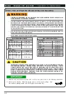
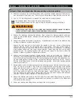
Page 48: ...EFORE USE AFTER ONE HOUR OF UNLOADED USE OR AFTER FIRST LOAD AND EACH LOAD UNTIL WHEEL NUTS BOLTS MAINTAIN TORQUE VALUE CHECK TORQUE EVERY 10 HOURS OF USE THERE AFTER AFTER EACH WHEEL REMOVAL START TORQUE PROCESS FROM BEGINNING WARRANTY DOES NOT COVER FAILURES CAUSED BY IM PROPERLY TORQUED WHEEL NUTS BOLTS Remove only one wheel and tire from a side at any given time in the following procedure 1 Hi...

Page 49: ...nut to retain spindle to axle For walking tandem units use the hole closest to the hub to retain the spindle Tighten as outlined in Maintenance Section 6 Remove seal and inspect bearings spindle washer castle nut and cotter pin Replace if necessary Pack both bearings with approved grease and reinstall inner bearing Install new seal in hub with garter spring facing the hub by tapping on flat plate ...

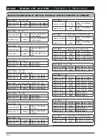
Page 50: ...Dual Wheels Factory CAL 24280 Single Dual Wheels Brent Model 1080 Factory Set Up 127075 Single Dual Wheels Tracks Factory CAL 24280 Single Dual Wheels Tracks Brent Model 1082 Serial Number B31270099 Lower Factory Set Up 127070 Single Dual Wheels Tracks Factory CAL 24280 Single Dual Wheels Tracks Brent Model 1082 Serial Number B31270100 Up Factory Set Up 127070 Single Dual Wheels Factory CAL 24280 ...

Page 51: ...et Up 128160 Single Wheels Tracks Factory CAL 40800 Single Wheels Tracks Factory Set Up 128120 Walking Tandem Factory CAL 40800 Walking Tandem Brent Models 1594 1596 Factory Set Up 128160 Tracks Factory CAL 40800 Tracks Factory Set Up 128120 Steerable Tandem Factory CAL 40800 Steerable Tandem Brent Model 2096 Factory Set Up 128160 Tracks Factory CAL 40800 Tracks Factory Set Up 128160 Steerable Tan...

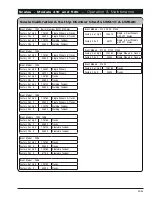
Page 52: ...28160 Single Dual Wheels Tracks Factory CAL 40800 Single Dual Wheels Tracks Factory Set Up 128120 Walking Tandem Factory CAL 40800 Walking Tandem Unverferth Model 1110 Factory Set Up 148070 Single Wheels Tracks with 3PT Scales Factory CAL 48727 Single Wheels Tracks with 3PT Scales Factory Set Up 127070 Tracks with 3PT Scales Factory CAL 24280 Tracks with 3PT Scales Factory Set Up 128160 Single Whe...

Page 53: ...ales Factory CAL 40800 Single Wheels Tracks with 5PT Scales Factory Set Up 128120 Walking Tandem Factory CAL 40800 Walking Tandem Unverferth Model 1610 1620 2020 Factory Set Up 128160 Tracks Factory CAL 40800 Tracks Unverferth Model 5225 Factory Set Up 137060 Single Wheels Factory CAL 23980 Single Wheels Unverferth Model 6225 Factory Set Up 127070 Single Wheels Factory CAL 24080 Single Wheels Unve...

Page 54: ...ory Set Up 128160 Single Wheels Tracks Factory CAL 40800 Single Wheels Tracks Factory Set Up 128120 Walking Tandem Factory CAL 40800 Walking Tandem Killbros Model 1613 Factory Set Up 128160 Tracks Factory CAL 40800 Tracks Parker Models 842 Factory Set Up 148070 Single Dual Wheels with 3PT Scales Factory CAL 48727 Single Dual Wheels with 3PT Scales Factory Set Up 128160 Tracks Factory CAL 40800 Tra...

Page 55: ...ge displayed is SETUP Next the actual SETUP number is displayed with the far right digit flashing Setup Number Example NOTE Refer to UM410 UM520 Scale Calibra tion Set Up Number Charts in this section for Set Up or CAL numbers 3 Press the START STOP key to select the far left digit as the flashing digit 4 Press the FIELD key to increment the flash ing digit Change the 1 to 5 5 Press the ON key to ...

Page 56: ...until the message displayed is SETUP then let up on the keys First message displayed is SETUP Next the actual SETUP number is displayed with the far right digit flashing 3 Press the ON key to advance to the CAL number The CAL message is displayed and then the CAL number CAL Number Example NOTE Refer to UM410 UM520 Scale Calibra tion Set Up Number Charts in this section for Set Up or CAL numbers 4 ...

Page 57: ...d them both together until the message displayed is SETUP then let up on the keys First message displayed is SETUP Next the actual SETUP number is displayed with the far right digit flashing 3 Press the START STOP key to select the 7 700000 as the flashing digit 4 Press the FIELD key to increment the flash ing digit Change the 7 to 8 800000 or desired higher number 5 Press ON to exit setup SETUP 1...

Page 58: ...ers To change CAL number Enter D A N code 872 press SELECT current CAL number will display Enter the new CAL num ber and press ENTER CAL number Example NOTE Refer to UM410 UM520 Scale Calibra tion Set Up Number Charts in this section for Set Up or CAL numbers 128120 40800 Downloader Module Optional For Optional Downloader Module operation procedures please refer to Digi Star downloader manual or g...

Page 59: ...from cart is displayed on 410 indicator Press Start Stop button and the indicator will display PRINT The weight of the grain remain ing in the grain cart will be displayed Cart operator can proceed back to the combine to receive additional grain 520 indicator with Auto Log When entering the field press FIELD to choose farm field Press ID to choose truck or wagon hauling grain Engage tractor PTO ra...

Page 60: ...anual The Short Form Set Up Calibration procedure allows you to change the SETUP and CAL numbers of the indicator You may want to perform this procedure if 1 The indicator is being connected to different load cells or 2 You want to adjust the calibration to match another scale system PLEASE NOTE Do not attempt to calibrate the scale if the indicator is not reading stable weights The calibration pr...

Page 61: ...ration This indicator has the ability to match any other scale even if that scale is uncalibrated To match your UNVERFERTH Scale Scale A to another scale Scale B you must determine the Calibration Multiplier To do this place a load on Scale A feed wagon etc and write down the weight displayed Repeat several times to determine the average weight Next place the same load on Scale B and again write d...

Page 62: ...er Enter D A N code 871 press SELECT current SETUP number will display Enter the new SETUP number and press ENTER To change CAL number Enter D A N code 872 press SELECT current CAL number will display Enter the new CAL num ber and press ENTER NOTE Refer to UM410 or UM520 Operator s manual for any indicator set up or troubleshooting information ...

Page 63: ...t damage the load cells or indicator if wires are shorted durn ing this step No Your indicator is probably not set up and cali brated correctly Check the decal on the bot tom of the indicator The decal shows what type of load cells the indicator was calibrated to By pressing the ON key while the indi cator is already on you will get the indicator s SET UP and CAL numbers Write these down and see i...

Page 64: ...mponents starting at the indicator and will continue to reconnect one component at a time working our way back towards the grain cart 2 Begin with the j block cable by reconnecting at the indicator and observe the indicator read ing The indicator should show little or no change If this changes dramatically or becomes unstable replace the cable 3 Next connect the opposite end of the j block cable t...

Page 65: ...ed Ensuring maximum accuracy Carts with compression load cells 1 Canister load cells must be standing straight up and down If leaning side to side or forward backward spacer washers will need to be added to shift the axle side to side or restrict excess axle movement FIG 3 1 FIG 3 2 ...

Page 66: ... cells both should make contact at nearly the same time If one load cell contacts significantly before the other a 1 16 shim 280396 will need to be placed under one load cell 3 To prevent load cells from rotating install an anti rotation bracket 283860 on top of each canister load cell Towards Center Line of Cart 1 8 or Less FIG 3 3 FIG 3 4 FIG 3 5 FIG 3 6 FIG 3 7 ...

Page 67: ...ister load cells the tractor drawbar and cart hitch casting and retainer pins that hold the cart axle to the cart body This will allow parts to move freely and will minimize any binding that may occur from load to load 7 Each canister cell sets inside a ring welded on top of the cart axle Rings on earlier produc tion carts have a set screw to prevent each cell from turning Any current production c...

Page 68: ...TART STOP button again to conclude the unload process The indicator will display PRINT showing the conclusion of the unload process and the weight that was displayed at that moment the amount unloaded from the grain cart will either print to an optional printer or be stored in the external memory module of the optional Data Downloader DDL kit if purchased Imme diately thereafter the indicator will...

Page 69: ...s with walking tandem undercarriages or carts with single rear tires wheels both use the same 3 3 4 diameter rear spindle with 2 drilled holes for mounting to the grain cart The walking tandem cart utilizes the spindle hole located closest to the hub 3 1 2 from end of spindle The carts with single wheels or steerable tandems utilize the spindle hole located farthest from the hub 2 1 4 from end of ...

Page 70: ...Scales Models 410 and 520 Operation Maintenance 3 24 Notes ...

Page 71: ... Load Cell Tracks All 5 Point Track Load Cell 1194 Single Wheels All 3 Point Spindles Tracks All 3 Point Compression Cells Walking Tandem All 5 Point Spindles Tracks All 5 Point Track Load Cell 1196 1396 Walking Tandem All 5 Point Spindles Single Wheels All 5 Point Single Wheel Load Cell Tracks All 5 Point Track Load Cell 1282 Single Wheels Serial Number B31270099 Lower 3 Point Spindles Single Whe...

Page 72: ...ial Number B31290099 Lower 3 Point Spindles 1015 1017 Rigid Axle Single Wheels Serial Number B31290100 Higher 3 Point Spindles Adjustable Axle Single Wheels Serial Number B31290100 Higher 5 Point Single Wheel Load Cell 1110 1152 9250 Manual Tensioning Tracks All 3 Point Compression Cells 1015 1115 1315 1117 1317 1119 1120 1320 1110 1310 1152 1352 Walking Tandem Duals All 5 Point Spindles 1115 1315...

Page 73: ...es All 3 Point Spindles 835 Single Wheels and Duals All 3 Point Spindles 835 1035 1135 Manual Tensioning Tracks All 5 Point Track Load Cell 1035 1135 Rigid Axle Single Wheels All 3 Point Spindles Adjustable Axle Single Wheels All 5 Point Single Wheel Load Cell 1111 1311 1113 1313 Walking Tandem Duals All 5 Point Spindles Single Wheels All 5 Point Single Wheel Load Cell 1111 1311 1611 1113 1313 161...

Page 74: ...r Range Scale Type 742 524 624 739 839 1039 All All 3 Point Spindles 842 Single Wheels and Duals All 3 Point Spindles Tracks All 5 Point Track Load Cell 1042 1142 1139 Rigid Axle Single Wheels All 3 Point Spindles Adjustable Axle Single Wheels All 5 Point Single Wheel Load Cell Tracks All 5 Point Track Load Cell 1048 Single Wheels All 3 Point Spindles Tracks All 5 Point Track Load Cell 1348 1154 1...

Page 75: ...h com parts for the most current parts listing SCALE PACKAGE PARTS Single Tires with 3 Point Scales Spindles 4 6 Single Tires with 3 Point Scales Compression Cells 4 14 Walking Tandem Steerable Tandems In Line Tandems 5 Point Scales 4 18 Tracks with 5 Point Scales 4 22 Single Tires 5 Point Scales 4 28 Rotational Sensor Mounting Kit For UM520 Scale 4 32 ...

Page 76: ... 6 Please visit www unverferth com parts for the most current parts listing Single Tires with 3 Point Scales Spindles Components 50 7 7 Model UM410 Please visit www unverferth com parts for the most current parts listing Model UM520 63 ...

Page 77: ...1017 1119 1139 V1100 Models 1110 1310 1115 1315 Serial Number B31290199 and Lower 3 250843 Hitch Pin 1 Dia x 4 9 16 1 Models 739 1175 7250 8250 1175 1185 739 839 250844 Hitch Pin 1 Dia x 4 1 8 1 Models 576 678 282876 Hitch Pin 1 Dia x 5 1 2 1 Models 1015 1017 9250 1195 1950 1039 1048 4 91192 Retaining Ring 1 2 Model 576 678 1015 1017 7250 8250 9250 1175 1185 1195 1950 739 839 1039 1048 5 9006347 S...

Page 78: ...els 1110 1115 Serial B31290199 Lower 251817 UM520 Indicator Scale Box Models 1310 1315 Serial B31290199 and Lower 29547 UM520 Indicator Scale Box Models 7250 8250 9250 1175 1185 1195 739 839 1039 For Singles 29551 UM520 Indicator Scale Box Models 7250 8250 1175 1185 739 839 For Duals 29553 UM520 Indicator Scale Box Models 9250 1195 1039 1048 For Duals 9005981 UM520 Indicator Scale Box Model 1950 1...

Page 79: ...dels 5225 6225 1150 1160 524 624 18 9390 198 Capscrew 1 8UNC x 7 1 2 1 Models 5225 6225 1150 1160 524 624 19 9390 199 Capscrew 1 8UNC x 8 1 Models 7250 8250 9250 1175 1185 1195 739 839 1039 20 9404 041 Lock Washer 1 2 Models 7250 8250 9250 576 5225 6225 1150 1160 1175 1185 1195 1950 524 624 739 839 1039 1048 21 9394 020 Hex Nut 1 8UNC 2 Models 7250 8250 9250 576 5225 6225 1150 1160 1175 1185 1195 ...

Page 80: ...5 1017 7250 8250 9250 1175 1185 1195 739 839 1039 V700 V800 V1000 V1100 Models 1110 1310 1115 1315 Serial Number B31290199 and Lower 52 9390 003 Capscrew 1 4 20UNC x 3 4 2 Models 1015 1017 7250 8250 9250 1175 1185 1195 739 839 1039 Models 1110 1310 1115 1315 Serial Number B31290199 and Lower UM520 Mounting Bracket Hardware 53 9394 002 Hex Nut 1 4 20UNC 2 54 9404 017 Lock Washer 1 4 2 55 9405 064 F...

Page 81: ...r 31290099 and Lower Killbros Models 1035 1135 Parker Models 1042 1142 1139 UM520 Scale Package Single Dual Wheels Brent Models V700 V800 V1000 Killbros Models 735 835 Parker Models 742 842 UM520 Scale Package Single Wheels Tracks Unverferth Model 1110 251822 UM520 Scale Package Duals Unverferth Models 7250 8250 Killbros Models 1175 1185 Parker Model 739 UM520 Scale Package Single Wheels Parker Mo...

Page 82: ...el 9250 For 36x32 Wheels Killbros Model 1039 For 144 Axle Parker Model 1195 For 144 Axle Parker Model 1048 284010 UM410 Scale Package Single Wheels Brent Model 1194 Unverferth Models 760 860 1015 1017 1019 1060 1160 1119 Unverferth Model 1115 Serial Number B31290099 Lower Killbros Models 1035 1135 Parker Models 1042 1142 1139 UM410 Scale Package Single Dual Wheels Brent Models V700 V800 V1000 V110...

Page 83: ...Scales Models 410 and 520 Parts 4 13 Please visit www unverferth com parts for the most current parts listing Notes ...

Page 84: ...lease visit www unverferth com parts for the most current parts listing Single Tires with 3 Point Scales Compression Cells Components 23 8 8 39 Please visit www unverferth com parts for the most current parts listing Model UM410 Model UM520 ...

Page 85: ...6 9004909 Compression Cell w 30 Cable 2 Models 782 882 1082 7 9000107 Cable Ties 15 1 2 Lg A R Models 782 882 1082 8 9005465 UM410 Indicator Scale Box 1 Model 782 882 1082 9005981 UM520 Indicator Scale Box Model 782 882 1082 9 903172 119 Pan Head 8 32UNC x 1 1 4 Phillips 3 Models 782 882 1082 10 9404 011 Lock Washer 8 3 11 9405 046 Flat Washer 8 3 12 9830 015 Hex Nut 8 32 3 13 9005259 O Ring 1 Mod...

Page 86: ...ounting Bracket 1 Models 782 882 1082 42 9390 003 Capscrew 1 4 20UNC x 3 4 2 Models 782 882 1082 UM520 Mounting Bracket Hardware 43 9394 002 Hex Nut 1 4 20UNC 2 44 9404 017 Lock Washer 1 4 2 45 9405 064 Flat Washer 1 4 2 46 9512 Screw Self Drilling 1 4 14 x 1 2 47 9005936 Ram Mount Kit Models 782 882 1082 48 9005922 Ram Mount 1 49 9005935 Screw 10 32 4 50 9398 003 Elastic Stop Nut 4 51 283856 Spac...

Page 87: ...Scales Models 410 and 520 Parts 4 17 Please visit www unverferth com parts for the most current parts listing Notes ...

Page 88: ...ls 410 and 520 Parts 4 18 Please visit www unverferth com parts for the most current parts listing Walking Tandems Steerable Tandems In Line Tandems with 5 Point Scales Components 33 16 7 7 Model UM410 Model UM520 ...

Page 89: ...1111 1311 1348 1152 1352 1154 1354 9004913 Hitch Bar Scale 3 3 4 Dia Ref 404760 Model 2096 9004910 Hitch Bar Scale 3 3 4 Dia CAT 4 Model 2020 CAT 4 9008119 Hitch Bar Scale 3 3 4 Dia CAT 5 Model 2020 CAT 5 Model 2096 CAT 5 w Tracks 9008135 Hitch Bar Scale 3 3 4 Dia CAT 5 Model 2096 CAT 5 w Walking Tandem 3 282876 Hitch Pin 1 Dia x 5 1 2 1 Models 1110 1310 1015 1115 1315 1017 1117 1317 1282 1196 139...

Page 90: ...317 1196 1396 1596 1152 1352 14 9002130 Split Tension Bushing 2 Dia 1 Models 1110 1310 1015 1115 1315 1017 1117 1317 1196 1396 1596 1152 1352 15 9006278 Kit Universal EZ Mate 1 Model 1113 1313 1120 1320 1154 1354 2020 NOT SHOWN UM520 Scale 9006049 Kit Universal EZ Mate 1 Models 1110 1310 1113 1313 1015 1115 1315 1117 1317 1120 1320 1282 1196 1396 1111 1311 1348 1152 1352 1154 1354 16 9004925 J Blo...

Page 91: ...0 1310 1015 1115 1315 1017 1117 1317 1282 1196 1396 1596 2096 1152 1352 41 9005922 Ram Mount 1 42 9005935 Screw 10 32 4 43 9398 003 Elastic Stop Nut 4 44 9007122 Cable Splice Repair Kit Models 1110 1310 1015 1115 1315 1017 1117 1317 1282 1196 1396 1596 2096 1152 1352 NOT SHOWN 45 9005829 Memory Stick 1 Models 1110 1310 1015 1115 1315 1317 1282 1196 1396 1596 2096 1152 1352 NOT SHOWN 46 9006083 Sel...

Page 92: ...es Models 410 and 520 Parts 4 22 Please visit www unverferth com parts for the most current parts listing Tracks with 5 Point Scales with Hydraulic Tensioning Components 40 8 8 23 Model UM410 Model UM520 9A ...

Page 93: ...10 and 520 Parts 4 23 Please visit www unverferth com parts for the most current parts listing Tracks with 5 Point Scales with Hydraulic Tensioning Components Model 1082 Only Continued on next page 3 4 5 21 20 2 4 3 5 ...

Page 94: ...2 1352 271881B UM520 Scale Package In Line Tandem Model 2020 CAT 5 2007520 UM410 Scale Package Tracks Killbros Model 1950 2007521 UM520 Scale Package Tracks Killbros Model 1950 1 282875B Scale Hitch 1 Models 1110 1310 1610 1015 1115 1315 1017 1117 1317 1050 1082 1182 1282 1186 1386 1196 1396 1596 2096 1950 1152 1352 282329B Scale Hitch CAT 5 Model 2020 CAT 5 2 9004910 Hitch Bar Scale 3 3 4 Dia Ref...

Page 95: ...6 1596 2096 1950 1111 1311 1611 1139 1142 1348 1648 1154 1354 1654 1019 1119 1319 1519 V1500 1152 1352 2020 284287 UM410 Indicator Scale Box Models 1110 1310 1610 1113 1313 1613 1015 1115 1315 1017 1117 1317 1120 1320 1620 1050 1082 1182 1282 1186 1386 1196 1396 1596 2096 1950 1111 1311 1611 1139 1142 1348 1648 1154 1354 1654 1019 1119 1319 1519 V1500 1152 1352 9A 903172 120 Pan Head 8 32UNC x 1 1...

Page 96: ...50 1152 1352 21 92199 Center Locknut 1 8UNC 14 Models 1110 1310 1610 1015 1115 1315 1017 1117 1317 1050 1082 1182 1282 1186 1386 1196 1396 1596 2096 1950 1152 1352 22 9006278 Kit Universal EZ Mate 1 Model 1113 1313 1120 1320 1154 1354 2020 NOT SHOWN 9006049 Kit Universal EZ Mate 1 Models 1110 1310 1610 1113 1313 1613 1015 1115 1315 1017 1117 1317 1120 1320 1620 1050 1082 1182 1282 1186 1386 1196 1...

Page 97: ... 1017 1117 1317 1050 1082 1182 1282 1186 1386 1196 1396 1596 2096 1152 1352 44 9394 002 Hex Nut 1 4 20UNC 2 45 9404 017 Lock Washer 1 4 2 46 9405 064 Flat Washer 1 4 2 47 9512 Screw Self Drilling 1 4 14 x 1 2 48 9005936 Ram Mount Kit Models 1110 1310 1610 1015 1115 1315 1017 1117 1317 1050 1082 1182 1282 1186 1386 1196 1396 1596 2096 1152 1352 49 9005922 Ram Mount 1 50 9005935 Screw 10 32 4 51 939...

Page 98: ...Scales Models 410 and 520 Parts 4 28 Please visit www unverferth com parts for the most current parts listing Single Tires with 5 Point Scales Components 33 16 7 7 Model UM410 Model UM520 ...

Page 99: ...1111 1311 1139 1348 1019 1119 1319 V800 V1300 Model 1017 Only with 76 50 00 x 32 Tires Models 1110 1310 1152 1352 Serial Num ber B31290100 and Higher Model 1015 Serial Number B31290100 and Higher Only with 76 50 00 x 32 Tires Models 1115 1315 Serial Number B31290100 and Higher 1 282875B Scale Hitch 1 Models 1110 1310 1015 1115 1315 1017 1117 1317 1050 1182 1282 1186 1386 1196 1396 1152 1352 2 9004...

Page 100: ... Model 1017 Only with 76 50 00 x 32 Tires Models 1110 1310 1152 1352 Serial Num ber B31290100 and Higher Model 1015 Serial Number B31290100 and Higher Only with 76 50 00 x 32 Tires 284287 UM410 Indicator Scale Box 1 Models UM1160 KB1135 P1142 1110 1310 1113 1313 1115 1315 1117 1317 1120 1320 1050 1154 1354 1182 1282 1186 1386 1196 1396 V800 V1000 V1100 V1300 1111 1311 1139 1348 1019 1119 1319 1152...

Page 101: ...e 31 9004152 Interface Cable 1 Long 33 9005375 UM410 Mounting Bracket Replacement 2 Models UM1160 KB1135 P1142 1110 1310 1015 1115 1315 1017 1117 1317 1050 1182 1282 1186 1386 1196 1396 V800 V1000 V1100 1152 1352 Comes with Indicator Scale Box 34 200159B UM520 Mounting Bracket 1 Models UM1160 KB1135 P1142 1110 1310 1113 1313 1015 1115 1315 1017 1117 1317 1120 1320 1050 1154 1354 1182 1282 1186 138...

Page 102: ...ASE DWG BY CONTROL DATE WEIGHT PAINT SQ INCHES ALL DIMENSIONS INCHES UNLESS NOTED TOLERANCE 010 DECIMAL FRACTIONAL ANGULAR B BLACK LOW GLOSS CN06363 REVISION DATE 8 6 2015 2 46 PM 0 2 lbmass 1 16 SR CN06363 johnwa 281894 THIS DRAWING IS PROPERTY OF AND MAY NOT BE REPRODUCED IN ANY FORM 8 6 2015 8 6 2015 2 46 PM 15 5 BRACKET RPM SENSOR 1 FINISH POWDER COAT 0 SHEET 1 OF 1 6 7 8 REF 15 16 REF 1 5 32 ...

Page 103: ... 4 Gr 5 2 10 252065B RPM Sensor Flat Plate Black 1 For Single Dual Auger Carts Serial Number B34930099 and Lower Excluding 1048 Model 11 252198B RPM Sensor Bracket Black 1 12 252199B RPM Sensor Bracket Black 1 14 9006076 Proximity Sensor w Metri Pack Connector 1 15 9005981 UM520 Scale Indicator 1 16 9006131 Cable 16 Extension Proximity Sensor 1 17 9006132 Cable Y 1 18 900571 Hose Clamp 1 19 281894...

Page 104: ...NUALS 266900 September 2015 2 March 2016 3 July 2016 4 September 2016 5 November 2016 6 May 2017 7 May 2018 8 October 2018 9 March 2019 10 May 2019 11 September 2019 12 November 2019 13 www unverferth com ...

Reviews: