1.
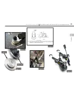
The retractable wheelchair tie-down should first be fitted as indicated on page 18-19
1.
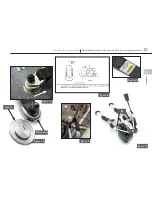
The self-retracting wheelchair tie-down should first be fitted as indicated on page 20-21
2.
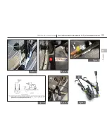
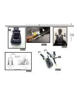
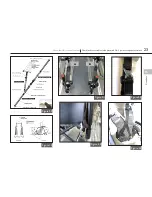
The occupant restraint should be installed in accordance with section B and C notes using the supplied hardware
(Fig 25).
Note:
if fitting hardware, other than that provided in this kit, is to be used then the fixing bolts should
be of an equivalent cross section and an equivalent grade namely B.S. Grade 'S' (ISO 8.8).
3.
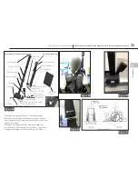
The componentry is assembed (Fig 25), with the upper 3rd point and lower reel anchorage points bolted to
an approved anchorage position on the vehicle body.
Note:
the upper 3rd point may be reversed as required,
by unclipping the buckle from the drop link tongue, reversing, and clipping back together. The inertia reel
should be mounted at an angle of 90°/90° as viewed in 2 planes to the road level (see inset photo opposite).
The reel and its bracketry is bolted through the vehicle and reinforced on the underside, if required, with the
100mm diameter load spreader plate and nyloc nut. All bolts should be tightened to a torque of 40Nm.
Note:
all vehicle anchorage points may require reinforcement as necessary to meet any required minimum strength
recommendations for the vehicle.
4.
Once installed, check the free running of webbing into and out of the inertia reel and check the 'lock up' facility
of the reel by engaging a short tug at various intervals along the extension and retraction of the webbing in and
out of the reel.
5.
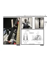
Adjust the drop link position at or above the shoulder height to comfortably suit the user, and draw the running
tongue across the occupant, through the furthest arm of the wheelchair and connect into the far side Quattro
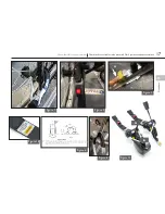
stalk to form a diagonal belt, (Fig 26). Disconnect the fixed tongue from its buckle attached to the inertia reel,
(Fig 27), pass it through the near arm of the wheelchair and connect back into the rearside Quattro stalk forming
the complete lap and diagonal, (see Figs 26 & 27).
6. The lap belt anchor points should be positioned to achieve belt angles of 30° or more to the horizontal and
preferably between 45° and 75° in order to fit low across the pelvis, reducing the possibility of the belt loading
the abdomen, (Fig 10). The pelvic restraint is designed to bear upon the bony structure of the body and should
be worn low across the front of the pelvis with any junctions between the pelvic and shoulder restraints located
near the wearer's hips.
7.
Place the wrap around the drop link and secure the Velcro to tidy the loose webbing end, (Fig 28).
Fitting and using the combined retracting and self-retracting tie-down
with 3 point WAV retractable occupant restraint
Fit and use
Floor anchors
3 Point Retractable Occupant Restraint:
Removing occupant restraint
1. Unfasten the buckle from
the stalks, remove the
occupant restraint and let
the webbing retract back
into the housing.
2. The wheelchair tie-down
should now be removed as
indicated on page 18 or 20.
24
Combined retractable tie-downs with 2 & 3 point occupant restraints
Wheelchair & occupant restraint

