background image

 

Unwin recommends the use of a 3 point occupant restraint system to provide greater protection 
in case of an impact. However we also recognise that some vehicle layout/designs or specific  
postural or medical conditions do not allow that style of seatbelts to be used easily.  

 

This system is not ISO 10542 compliant if used in 2 point configuration. 

 

Before fitting the occupant restraint, ensure that the reversible stalk orange button is facing  
outside in relation to the wheelchair. If the reversible stalk orange button faces inside, turn the 
stalk 180º to sit in the right position. 

 

In accordance with International regulations, standard Unwin occupant restraints are designed 
to be used for passengers weighing 22kg or above. If the passenger weighs less than 22kg, Unwin 
recommend that a suitable, and appropriately tested child restraint seat is used. This may in-
volve a secondary seat belt restraint as recommended by the original seat  
manufacturer. 

Fitting the Combined System - 3 Point Occupant Restraint   

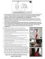
1.  Position the third point fixing into the cant rail (Fig 12) so that it is 

vertically above the inertia reel casing fixed onto the floor fixing.  
Unfasten the tongue and buckle. 

2.  Pull the black webbing upwards and unfasten the tongue from the 

red webbing buckle. 

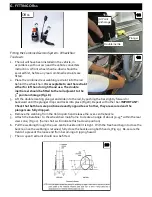
3.  Position the black webbing to form the lap belt and insert the 

tongue into the buckle stalk (Fig 13). 

4.  Ensure that the lap belt lays low on the pelvis of the occupant,  

running as close as possible over the hips on both sides. 

5.  Remove the black plastic cover on the red shoulder belt tongue and 

fit into the third point fixing. 

6. 

Position the red webbing to form the shoulder belt and insert the 
buckle into the tongue.


7. 

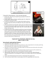
Adjust the height of the shoulder belt to clear the occupant’s  
shoulder by approximately 25mm (1 inch) Fig 14. 


8.  The lap belt anchor points should be positioned to achieve belt  

angles of 30° or more to the horizontal and preferably between 45° 
and 75° in order to fit low across the pelvis reducing the possibility 
of the belt loading the abdomen (Fig 11). The pelvic restraint is  
designed to bear upon the bony structure of the body and should be 
worn low across the front of the pelvis with any junctions between 
the pelvic and shoulder restraints located near the wearers hips. 

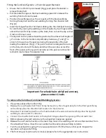
Important: For wheelchairs with fixed armrest,  

please contact Unwin. 

11 

Cant 

Rail 

12 

13 

14 

Summary of Contents for OR01

Page 1: ...s manual for future reference Please include it with the product in the event of transfer to new users Additional copies are available upon request Unwin House The Horseshoe Coat Road Martock Somerset...

Page 2: ...ns 6 The development of Unwin wheelchair tie downs and occupant restraints is a continuous process Applications are added on a regular basis For more detail contact Unwin or look on the Unwin website...

Page 3: ...er belt anchorage must be roof or side wall anchored at a height level such that the belt webbing passes over the midpoint of the occupant shoulder and at a height that is at or just above the level o...

Page 4: ...3 and push firmly down and towards the wheelchair until the yellow plunger drops and locks into the rail Ensure that each ATF is sited opposite each other 4 Remove the webbing from the Velcro patch a...

Page 5: ...ate an angle of about 30 45 within the rear view zone Fig 5 Some chairs will indicate this tie down position 8 Pull the webbing through the over centre buckle until it is tight With the free hand begi...

Page 6: ...the wheelchair main frame to create an angle of about 30 45 within the rear view zone Fig 11 Some chairs will indicate this tie down position If using tongue and buckle press the red buckle button s...

Page 7: ...t is vertically above the inertia reel casing fixed onto the floor fixing Unfasten the tongue and buckle 2 Pull the black webbing upwards and unfasten the tongue from the red webbing buckle 3 Position...

Page 8: ...the body and should be worn low across the front of the pelvis with any junctions between the pelvic and shoulder restraints located near the wearers hips To remove the Combined RearTie Down 1 If req...

Page 9: ...rd or backward until the plunger drops and locks into place Fig 18 Repeat with other bar IMPORTANT Check that both bars are positioned exactly opposite each other they are secured and the plungers are...

Page 10: ...it is vertically above the inertia reel casing fixed onto the floor fixing Unfasten the tongue and buckle 2 Pull the black webbing upwards and unfasten the tongue from the red webbing buckle 3 Positio...

Page 11: ...nd should be worn low across the front of the pelvis with any junctions between the pelvic and shoulder restraints located near the wearers hips Important For wheelchairs with fixed armrest please con...

Page 12: ...ome raising the anchor from its housing if using the retractable Solar floor anchor and rotate the cleat through 90 Fig 29 to align the karabiner with the wheelchair frame Install the second rear tie...

Page 13: ...t is vertically above the inertia reel casing fixed onto the floor fixing Unfasten the tongue and buckle 2 Pull the black webbing upwards and unfasten the tongue from the red webbing buckle 3 Position...

Page 14: ...ss the front of the pelvis with any junctions between the pelvic and shoulder restraints located near the wearers hips Important For wheelchairs with fixed armrest please contact Unwin To remove the S...

Page 15: ...them immediately 3 All webbing and components can be cleaned as necessary but care should be taken to prevent contamination of the webbing with polish oils and chemicals particularly acid alkalis and...

Page 16: ...Unwin House The Horseshoe Coat Road Martock Somerset TA12 6EY UK Tel 44 0 1935 827740 Fax 44 0 1935 827760 Email sales unwinsafety com Website www unwinsafety com...

Reviews: