background image

1

9

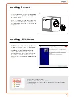
Installing Filament

1.  To install the filament spool, open the magnetic 

cover and insert the filament into the guiding tube 
at the spool holder.

2.  Push the filament into the guiding tube until 

it comes out from the other end. Put the spool 
onto the cassette and cover the spool with the 
magnetic cover.

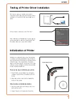
Installing UP Software

1.  Go to the support section of www.pp3dp.com to 

download the latest version of the UP Software.

2.  Double-click the setup .exe file to install the 

software. (The default installation path is C:\
ProgramFiles\UP.) A pop-up window will appear. 
Select "Install" and follow the instructions to 
finish. The printer’s driver is now installed into the 
system.

After installation, in the UP folder:
The Driver folder contains the printer drivers
The Example folder contains STL files for the printed parts of the UP printers 
and example files.

Summary of Contents for BOX pp3dp

Page 1: ...1 USER MANUAL FOR UP BOX ...

Page 2: ...ion of printer Automatic Platform Calibration Automatic Nozzle Height Detection Coarse Manual Platform Leveling Prepare for Printing Printer Control Buttons LED Light Bar Software Interface Loading a Model Printing Progress Pause of Print Job Rotate a Model Duplicate Model Moving Model 4 5 7 8 8 9 9 10 10 11 12 13 14 15 15 16 17 19 19 20 20 21 Table of Contents ...

Page 3: ...arameters Repairing a Model Calibration for the Correct Dimensions Change Software Language Printing Techniques Maintenance Fine Manual Calibration Controllimg Multiple Printers Troubleshooting UP BOX Specifications 22 23 24 25 26 27 28 29 30 33 34 35 2AAHW 3DP 25 ...

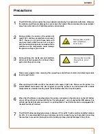
Page 4: ...ith ABS and PLA the plastics will create a light odor Please run the printer in a well ventilated environment We also suggest you put the printer in an environment with a stable temperature as unwanted cooling could cause adverse effects to the print quality When the UP software is sending data to the printer indicated on the status bar on the left bottom corner of the software interface with the ...

Page 5: ...5 Spool Holder Magnetic Cover Filament Spool Top Lid Front Door Initialization Button Extrude Withdraw Button Pause Stop Button Power Interface USB Interface Power Switch Printer Body ...

Page 6: ...6 X Axis Y Axis Z Axis Print Platform LED Bar Air Filter Print Head Mount Automatic Leveling Probe Magnets Print Head Nozzle Metal Plate Nozzle Height Detector ...

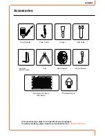
Page 7: ...ys 2 0mm 2 5mm Power Adapter USB Cable Scraper Power Cable Perforated Print Board Perf Board Print Head Nozzle All accessorise may subject to change without prior knoedegent If anything is missing please contact your local distributor at support pp3dp com ...

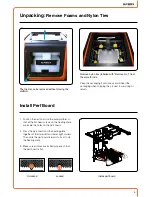
Page 8: ...rvicing or return Install Perf Board 1 Position the perf board on the build platform so that all the flat head screws on the heating plate are inside the holes on the perf board 2 Press the perf board and the heating plate together at the lower left and lower right corners Then slide the perf board forward to lock it onto the heating plate 3 Make sure all holes are locked properly so that the perf...

Page 9: ...re 1 Go to the support section of www pp3dp com to download the latest version of the UP Software 2 Double click the setup exe file to install the software The default installation path is C ProgramFiles UP A pop up window will appear Select Install and follow the instructions to finish The printer s driver is now installed into the system After installation in the UP folder The Driver folder cont...

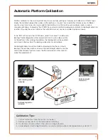
Page 10: ...ad and print platform move slowly and hit the endstops of the XYZ axes This is essential as the printer needs to find the endpoints of each axis The other software options will light up and become available for use only after initialization Initialization Button There are two ways to initialize your printer 1 The UP BOX can be initialized by clicking the Initialize option in the software menu show...

Page 11: ...probe will be lowered and start to probe nine positions on the platform After probing the platform the leveling data will be updated and stored in the machine The leveling probe retracts automatically Nozzle height detection will be started automatically after the end of auto leveling The print head will move toward the nozzle height detector and the nozzle will eventually touch and press the thin...

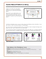
Page 12: ...ling this may be due to a severe unleveling of the platform which exceeds the capability of the auto leveling function In this case you should perform a coarse manual leveling before auto leveling see next page You may also level the platform without using the auto leveling and nozzle detection functions Please refer to P 30 for details During nozzle height detection the print head nozzle will tou...

Page 13: ... piece of paper to determine the correct platform height Try to move the paper and feel its drag between the platform and the nozzle Make sure you can feel the similar drag resistance at all five positions by moving the print head and adjusting the screws while the platform height is fixed Platform too high nozzle is pinning paper onto the platform Lower the platfrom slightly Just right Can feel s...

Page 14: ...l reach 260 C then the printer will buzz and the print head will start to extrude Gently insert the filament into the small hole on the print head The filament will be fed into the print head automatically when it reaches the extruder gear inside the print head Check the nozzle for plastic extrusion If plastic is coming out from the nozzle that means the filament is loading correctly and the print...

Page 15: ...PAUSE RESUME STOP Blue Pulsing Blue Letter Rotation Green Pulsing LED Light Bar LED Light Bar Printer switched on waiting to be initialized Printer initialized waiting for job Fast Print job spooling from computer Slow Printing Print job paused Orange Pulsing Red Pulsing Error Single Letter Remains On SD Card Error Platform Temprature Error Print Head Temperature Error Motion System Error Print He...

Page 16: ...mode Machine will enter sleeping mode if it is being idled for 2 minutes when it is not initialized Single press the initialization button can exit the sleeping mode Sleeping mode is only available in certain countries if machine does not enter sleeping mode may not indicate malfunction LED Light Bar ...

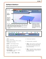
Page 17: ...old moving mouse to move print plate Mouse wheel could scale the print plate view The print plate size depends on the printer model connected to 1 2 3 4 5 6 7 8 9 10 11 Open Save Unload Print About 8 Set the value of adjustments 9 Set the orientation of adjustments 10 Place Place the model on the center of the print plate If more than one model is loaded the software will optimize their positions ...

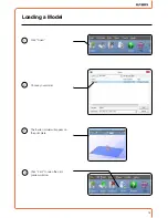
Page 18: ...18 Click Open Choose your model The loaded model will appear on the print plate Click Print to open the print preview window Loading a Model 1 2 3 4 ...

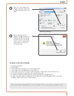
Page 19: ... Print Preview Interface 1 Printer model selection 2 Nozzle height 3 Click to enter printer preferences to set printing parameters 4 If your model is not solid defective turn this option on 5 No raft will be printed if this is turned on Platform leveling compensations will be disabled as well 6 Print Quality the better the print quality the slower the print speed 7 Set the pause height The printer...

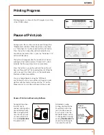
Page 20: ...Print for resuming the print While the print is paused the other buttons on the maintenance interface will become available You can change filaments using the Withdraw and Extrude buttons or move the print head and print platform with the location buttons and the To button Make sure not to crash the print head into the model Pause of Print Job without using Software During printing when the front ...

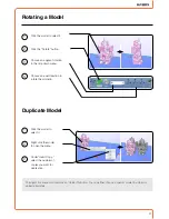
Page 21: ... axial direction to rotate the model in 1 2 3 4 Duplicate Model Click the model to select it Right click the model to open the menu Under Insert Copy select the number of copies you want for duplication The right click menu also contains an Unload function You can either choose a specific model to unload or unload all models 1 2 3 ...

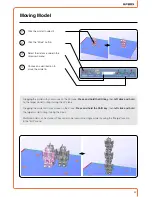
Page 22: ...your mouse on the Z axis Press and hold the Shift key then left click and hold the target model to drag it along the Z axis Multiple models can be stacked They can also be fused into a single model by using the Merge function in the Edit menu Click the model to select it Click the Move button Select the distance value in the dropdown menu Choose an axial direction to move the model in 1 2 3 4 ...

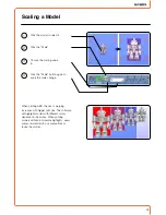
Page 23: ...button again to apply the scale change 1 2 3 4 When printing ABS the risk of warping increases with bigger print size The software will highlight models with different colors depends on their sizes When printing models with red and purple highlights users are recommended to use precautions or resize the model ...

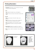
Page 24: ...w many layers will be made for the bottom of the model 3 Support Dense How many layers will be created for dense support generation Space Set the density of the support structure The higher the value the less dense the supporting structure becomes Area If the supporting area is less than this value no support will be generated You can turn off support by choosing Only Base 4 Stable Support Generat...

Page 25: ...e finish Infill The inner structure of the printed object The density of the infill can be adjusted Raft The thick structure that assists with the adhesion of the object to the platform Surface The bottom layers of the printed object Suppot Range 30o Support Range 80o Dense support Dense support Surface Print Platform Infill Support Raft ...

Page 26: ...el contains defective surfaces the software will highlight the surfaces in red After selecting the model select Edit Fix to automatically repair the model The red defective surfaces will resume a normal color when repaired If the model cannot be repaired please use other 3D modeling or mesh modifying tools to repair it 1 2 3 ...

Page 27: ...ding feedback to the software Load and print the calibration model C ProgramFiles UP Example Calibrate96 UP3 Manually measure the printed model as shown in the calibration window Input the measured values into the software and finish the calibration Open 3D Print Calibrate This will open the calibration panel Hit Reset button to revert the values back to default make sure the upper panel dispaly X...

Page 28: ...ing following hot keys Press the key combination then close the software the language will change after the software is opened next time Hot Keys to Change Language Alt Ctrl N E F J I System Language English French Japanese Indonesian S R T Spanish Russian Traditionl Chinese ...

Page 29: ...s adjustable There is a small lever on the fan duct When printing in PLA turn the lever counterclockwise to direct the airflow to the nozzle This will cool the PLA as soon as it is extruded and improve print quality When printing large object using ABS turn the lever clockwise to direct the airflow away from nozzle to slow down the cooling and to prevent warping Users could experiment with differe...

Page 30: ...inting whichever comes first Nozzle Wrench Removing the nozzle After a long period of printing the nozzle can become very dirty or even clogged You can replace it with a new one while the old one is cleaned for reuse 1 Use the Withdraw function in the Maintenance panel The nozzle will heat up to the printing temperature 2 Wear the heat resistant gloves provided in your printer kit and wipe the noz...

Page 31: ...4 Nine platform calibration point buttons After clicking these the nozzle will move to the corresponding positions The drop down menu beside the button is for setting the leveling compensation values Protocol for setting nozzle height Initialize the printer Put a print paper on the platform Open the calibration interface and press the up arrow key Note the current height value and stop raising the...

Page 32: ...atform height value Repeat steps 1 6 for all of the other eight positions and note their platform height values Platform Values at 9 calibration points hypothetical 1 208 2 208 5 3 208 7 4 208 6 5 208 9 6 209 7 208 8 8 208 9 9 208 8 When you have obtained the platform height values for all nine positions find the lowest value among the values In this example the first calibration point has the low...

Page 33: ...sition buttons will be available A compensation value between 0 1 0mm will be available for selection To calculate the compensation value Platform Height Nozzle Height Compensation Value For example setting the compensation value for calibration point 3 Assume the platform height is 208 7 and the nozzle height is 208 The compensation value should be set to 0 7 After setting 0 7 in the drop down me...

Page 34: ...h independent power supply is recommend to ensure stable connections User can define custom name to the connected printer at the print preference interface for easy idenfication Users can choose a single printer to control at 3D Print Printers menu After setting up the print user can choose another printer from the menu and so on Naming printer at print preference ...

Page 35: ...e print head There may be plastic clogged in the nozzle Replace the nozzle or remove the clog The filament may be too thick This usually happens when using a filament of poor quality Please use UP brand filament for quality assurance For some printer models PLA can present a consistent issue Switch to ABS My computer won t detect the printer Make sure the printer drivers are installed correctly Ch...

Page 36: ...grated leveling probe Print Surface Heated bed with perf board Unterthered Printing Yes Average Operational Noise 51dB Advanced Features Door Sensor Air Filtration Full Color LED Bar Bundled Software UP Software Compatible File Formats STL UP3 UPP Connectivity USB Operating System WinXP Vista 7 8 Mac OS Power adapter 110 240VAC 50 60Hz 220W Chassis Plastic case with metal frame enclosed Printer We...

Page 37: ...37 ...
Reviews: