UC-350E+ Encoder User’s Manual
8
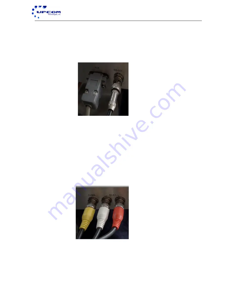
signal source equipment while the other end is connected to the Encoder’s SDI (BNC)
input interface. The Encoder’s SDI interface input port and its connected BNC cable is
illustrated below:
2.4.3 Unbalanced Audio and CVBS Video Input Connection
Users can find the CVBS and RCA interface input connectors on the device's rear panel.
If in doubt, refer to the rear panel illustration included in this manual (chapter 1.5). The
required CVBS and RCA interface cable is included in the device's packaging. One end
is connected to the signal source equipment while the other end is connected to the
Encoder’s CVBS and RCA input interfaces. The Encoder’s CVBS and RCA interface
input ports and its connected cables are illustrated below:
2.4.4 ASI Output Interface Connection
Users can find the ASI interface output connector on the device's rear panel. If in doubt,
refer to the rear panel illustration included in this manual (chapter 1.5). The required ASI
interface cable is included in the device's packaging. One end is connected to the


