

© UPLIFT Desk
• 800-349-3839 • 512-614-3152 • info@upliftdesk.com • upliftdesk.com
5
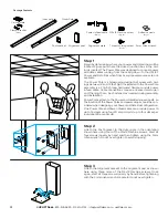
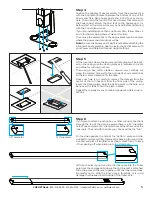
Step 5
At the locations where the power and data drops will be locat-
ed on the ceiling, use the Ceiling plate as a template to create
an outline for cutting your hole.
Then using a box cutter blade or drywall saw, carefully cut
along the marked hole just to the outside of your marked lines
so there is some clearance for the pole.
Once your hole is cut, carefully remove the material from the
center of the cut lines and, from the floor side of the ceiling,
insert the Ceiling plate. Hold the Ceiling plate in the hole, and
bend over the tabs to hold the plate in place.
Repeat these steps for any remaining power and data drop lo-
cations.
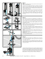
Step 6
If you plan to attach a junction box or other wiring connections
through the top of the pole, be aware there is a 1/2” diameter
hole at one end and a 3/4” diameter hole at the other end of the
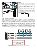
Inner pole. The end with the hole you choose will be the “top.”
On the side opposite the hole at the “bottom” place an Adhe-
sive pad to reduce rattling. Remove the backing from an Adhe-
sive pad and place it lengthwise as shown. Press firmly to keep
it from peeling off when sliding into the Outer pole.
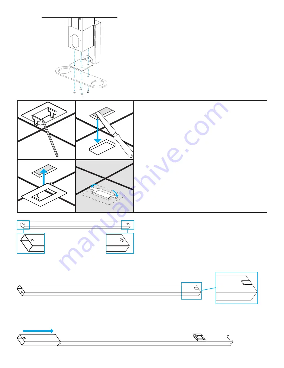
With both poles laying flat, slide the Inner pole into the Outer
pole from the end opposite where the Post bracket is attached.
Slide the poles all the way together until the Inner pole stops.
Be careful not to slide the Inner pole in forcefully or it could
damage the threaded inserts inside of the Outer pole.
1/2” diameter
3/4” diameter
Step 4
Position the Alignment post assembly from the previous step
with the Alignment bracket between the bottom of one of the
Power and Data Rail Square posts and a Post foot as shown
here. Then, using the four M5 Flat head screws that came with
the Square post, attach the Post foot to the Square post. As
before, start all four screws loosely by hand before tightening
with the 3mm Allen wrench.
If you are installing more than one Power Pole, follow Steps 2
and 3 for the remaining Power Poles at this time.
Then move the assemblies to the approximate locations below
where the power and data drops will be.
Note:
Be sure the Square post height is set before attaching the
Alignment post assembly. See the instructions that came with
your Power and Data Rail for post height settings.