


© UPLIFT Desk
• 800-349-3839 • 512-614-3152 • info@upliftdesk.com • upliftdesk.com
7
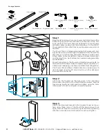
Step 10
Follow the instructions included with your Power and Data Rail
to begin adding rails and additional posts to your configuration.
Once the first Rail is in place, the length of cable coming out of
the Power Pole can be adjusted as needed to reach the Power
block in the rail. After the Power Infeed connection is made to
the Power block in the Rail, the excess cable above the ceil-
ing can be trimmed or coiled and electrical connections can be
made.
As noted in Step 6, the hole at the top of the Power Pole can
be used for attachment of a junction box or other wiring con-
nections.
To complete the wiring, have a licensed electrician connect the
“AC-95” 90° connector at the end of the Power infeed cable
to a 1/2” diameter knockout on the junction box and make the
applicable wiring connections.
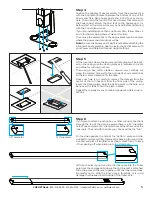
ITEM NO.
PART NUMBER
DESCRIPTION
QTY.
1
1
PRT00197
MAIN POLE
1
2
2
PRT00199
POWER POLE, BRACKET, ST
1
3
3 (x10)
90358A012
90358A012_METRIC STL ULTRA-
LOW-PROFILE SCKT HEAD SCREW
10
4
4
PRT00212
POWER POLE, CLAMP, ST
2
5
5
6
PRT00200
POWER POLE, LOWER TUBE, AL
1
6
PRT00207
POWER POLE, BRACKET, LOWER, ST
1
7
7
PRT00198
POWER POLE, INNER, AL
1
8
9
9 (x2)
8
PRT00206
???
POWER POLE, CEILING PLT, AL
Previously unmentioned screws
1
2
1
2
3 (x2)
3 (x5)
9 (x2)
3 (x3)
4 (x2)
5
6
7
8
1
2
3 (x10)
4
5
6
7
9 (x2)
8
1
2
3 (x2)
3 (x5)
9 (x2)
3 (x3)
4 (x2)
5
6
7
8
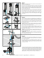
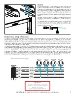
“AC-95” 90°
connector
Power infeed wiring information
The Power infeed accommodates up to four 20 amp circuits and consists of four line conductors, two neutrals, and two
grounds. Per National Electrical Code (NEC) requirements, up to 13 duplex receptacles may be used per circuit, with a total
of 52 available receptacles if all four circuits are used. The line conductors are 12 AWG, and share a 12 AWG ground and a 10
AWG neutral conductor. The fourth circuit is isolated and dedicated and is serviced by its own line, neutral, and isolated ground
conductors. The Byrne 8-Trac System can be wired in both single and three-phase configurations, 240/120V, 208/120V respec
-
tively (see Byrne 8-Trac wiring diagram below).
This power rail system utilizes (4) circuits; (3) for general purpose that share a common neutral and ground, and (1) circuit that
has a dedicated neutral and ground. This dedicated circuit is sometimes used as the “computer” circuit since it does not share
a neutral conductor, thereby reducing the chance for electrical noise originating from other loads that may be plugged in. But
many users plug their computers into any of the 4 circuits without issues. Byrne duplex receptacles are marked as 1, 2, 3, and
4. Receptacles marked 1, 2, and 3 connect to the three general purpose circuits and the receptacle marked 4 connects to the
dedicated circuit. IF you optionally choose to only plug computers into the dedicated circuit you may need to use additional
power infeeds and an electrical designer can help with this - as a general rule, you can assume 250W (2.08A) for each comput-
er receptacle and 180W (1.5A) for each general purpose receptacle when calculating for each 20A circuit.
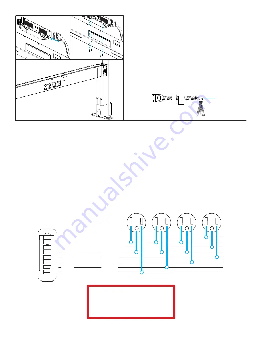
Hardwire power infeed wiring diagram
Circuit 1
Circuit 2
Circuit 3
Circuit 4
Gray
White
Green/Yellow
Green
Pink
Blue
Red
Black
Neutral 2
Neutral 1
Iso Ground
Ground
Hot 4
Hot 3
Hot 2
Hot 1
IMPORTANT:
All hard wired electrical connections
must be made by a licensed electrician.
Refer to all warnings
at the beginning of this manual.