Hardware installation
Making connections on the back panel
Back panel connections include:
Power
Power controller
Temperature sensor
Modem
Optional hardware authenticator
Connecting power
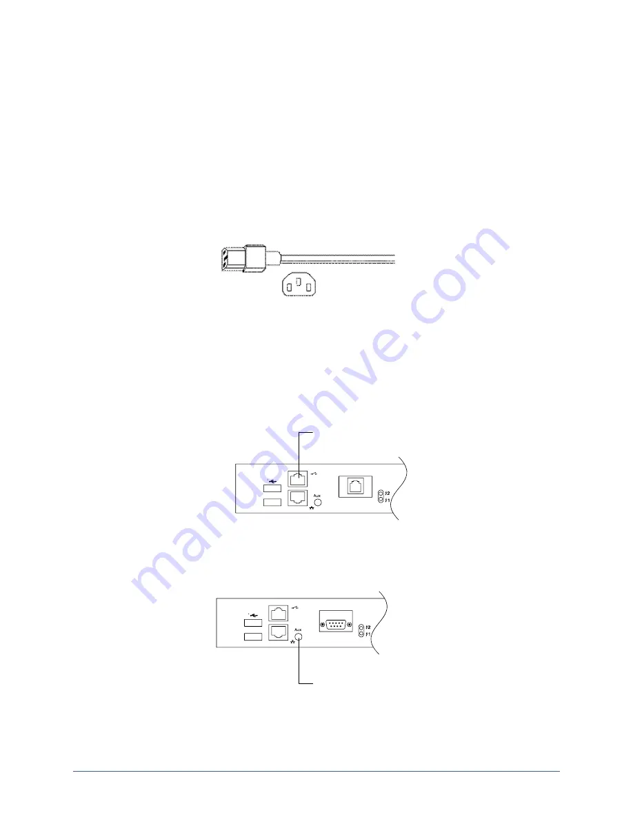
The appliance uses a power cord with a standard IEC-320-C13 female cord end.
Connect the power cord or cords to the unit and to appropriate power sources, then power on
the unit. The display and keypad on the front panel illuminate. As the appliance boots, it
displays progress messages.
At the end of the boot sequence, it displays the message
Uplogix status good
.
Connecting a power controller
Connect the power controller's serial port to the power controller port on the back panel of the
32-port appliance.
Connect power controller
Installing the optional temperature sensor
Secure the temperature sensor’s threaded connector to the 1-Wire® connector on the back of
the chassis.
Connect temperature sensor
Route the wire to the desired sensor location (for example, one of the posts on the rack) and
secure the sensor.
Installation Guide for Uplogix Secure Remote Management Appliances
7


