Hardware installation
Connecting power
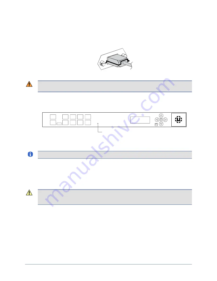
Connect the power cord to the power receptacle at the left rear of the appliance. If the
installation is subject to vibration, you may wish to attach the power cord retainer to the posts
on the power receptacle to hold the cord in place.
Connect the power cord to an AC power source, then power on the appliance.
Warning:
The plug-socket combination serves as the main disconnecting device and must be
accessible at all times.
Verify that the LCD displays progress messages and the battery indicator lights green to show
that the appliance is operating on external AC power.
battery indicator
At the end of the power-on sequence, the appliance displays the message
Uplogix status
good
.
Note:
When the appliance operates on battery power, the battery LED lights red.
Typical boot time is two or three minutes. When the Uplogix appliance has completed its boot
process, the front panel displays status information.
Connecting the modem
Connect the modem port to a standard analog (POTS) phone line provided by your local
telephone company for out-of-band dial-up support.
Caution:
Do not connect the on-board modem to digital PBX systems, VoIP analog terminal
adapters, or cellular modems. It is designed for use with analog telephone lines only. Uplogix
is not responsible for damage caused from attaching the modem to a digital phone switch.
Connecting a power controller
Connect a power controller to the power controller port on the back of the appliance.
The appliance can control a variety of managed power controllers. The power controller, used
to monitor and control power to the various network devices, completes visibility and low-level
control of the network device.
Each power controller has its own cabling requirements. Refer to the Reference Guide for
Uplogix Secure Remote Management Appliances
for wiring instructions for each of the
supported controllers.
22
Installation Guide for Uplogix Secure Remote Management Appliances


