www.uponor-usa.com • www.uponor.ca
14
Uponor Climate Co˘ntrol™ - Multifunction Installation Guide
15
Modulating Condensing Boilers
When there is a call for heat, the A terminal on boiler controls calls on
modulating (modcons) boilers. The Climate Co˘ntrol - Multifunction unit
cannot override the boiler settings through the A terminals. However, most
modcons allow a second input for domestic hot water (DHW) or other
high-temperature requirements. In these types of installations, the
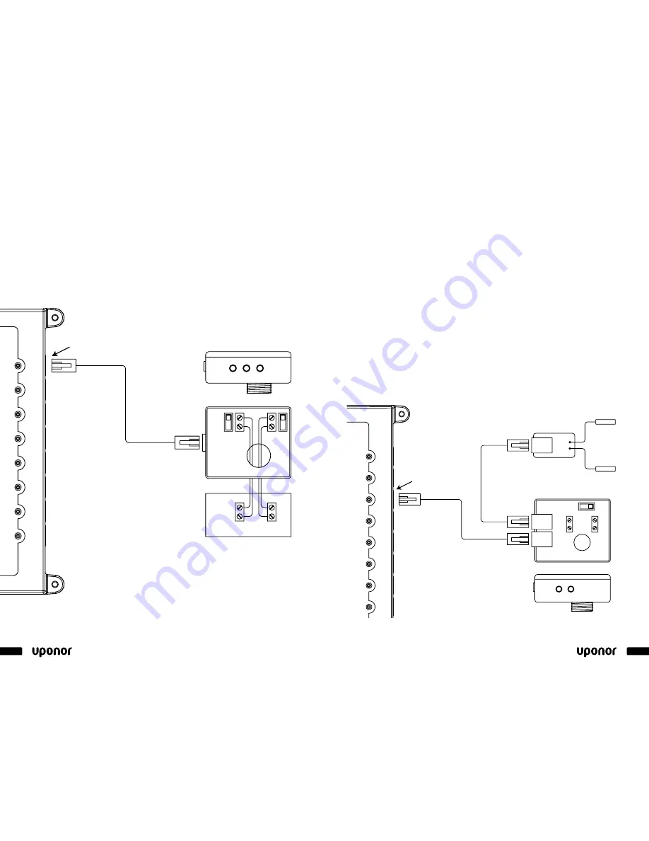
B terminals on the boiler control provide that function. (See
Figure 4-9
.)
Note:
Consult the boiler manufacturer’s installation and wiring instructions
to verify the high-temperature override.
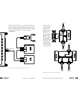
Figure 4-9
: Typical wiring of a heating device using boiler control for space heating
Auto
Man
A Terminal
B Terminal
A
B
Power
Space
High Temp
Heating
DHW
Typical heating device (e.g., boiler)
Top View
Side View
On
Tx
Run
Rx
Port 1
Input 1
Operate
MMI
Port 8
Input 8
Port 3
Port 2
Port 4
Port 5
Input 2
Input 3
Input 4
Input 5
Port 6
Input 6
Port 7
Input 7
Rx
Tx
Intercon
Boiler Control (A9012010)
To Climate Co˘ntrol Main Panel
Modulating Valves and Mixing
The Climate Co˘ntrol - Multifunction controller provides mixing and water
temperature control in secondary piping for lower temperature applications,
such as radiant floor heating and snow melting. The Climate Co˘ntrol hydronic
controller can connect to any 0-10VAC motor and valve using the Uponor
Modulating Valve Control (A9063020).
Note:
The motor must be 75 milliamps or less from a 24VAC supply or it
must be externally powered.
The Climate Co˘ntrol - Multifunction unit supports up to three separate water
temperatures, any combination of three for space heating and up to two
maximum for snow melting. Supply-and-return Dual Sensors (A9013001) are
plugged into the valve box using a Cat5 cable. (See
Figure 4-10
.) The ports
are not dedicated so any connection port can be used for connecting sensors
and cable to the Climate Co˘ntrol - Multifunction unit. These 10K sensors are
strapped or mounted to the secondary piping for temperature data to set the
proper position of the valve, based on outdoor temperature, load
requirements, etc.
Note:
Uponor stocks pre-assembled
3
/
4
" - 1
1
/
2
" valves.
Auto
Man
Power
Active
Top View
Side View
On
Tx
Run
Rx
Port 1
Input 1
Operate
MMI
Port 8
Input 8
Port 3
Port 2
Port 4
Port 5
Input 2
Input 3
Input 4
Input 5
Port 6
Input 6
Port 7
Input 7
Rx
Tx
Intercon
Return Sensor
Supply Sensor
GRN
(FB)
(Cntrl)
WHT
(Com)
BLK
(PWR)
RED
Uponor Modulating
Valve Control (A9063020)
Supply-and-return
Dual Sensors (A9013001)
To Climate Co˘ntrol
Main Panel
Figure 4-10
: Typical wiring of a modulating valve in a mixing application using Uponor
Modulating Valve Control (A9063020)


