background image

www.uponor-usa.com • www.uponor.ca

8

Uponor Climate Co˘ntrol™ - Multifunction Installation Guide

9

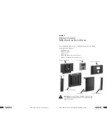
 The display and main control are packaged as a single unit, assembled and 
pre-wired for operation. Uponor recommends mounting the main control 
panel in the mechanical room or near the mechanical equipment it will 
operate to eliminate any unnecessary wiring. 

These tools and hardware are necessary for installation:

• Screws and/or anchor hardware for mounting
• Flathead and Phillips screwdrivers
• Wire cutters/strippers
• Level
• Thermostat wire, 18/2 AWG for connecting sensors
• Cat5 wire for connecting pumps, valves or boiler
•  Cat5 cable stripper (optional, but recommended if making custom cables)
• Cat5 cable tester

Mounting the Control Panel 

1.  Select a smooth, flat, uniform surface. 

2.  Select the proper screws and/or anchors for the 

surface. Four screws or anchors will properly 
secure the unit.

3.  Remove the side wings of the main control by 

loosening the four screws on the control unit. 
This will expose holes necessary to mount to  
the selected surface.

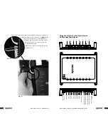
4.  Install the first screw semi-tightly so the control 

can be rotated. (See

 Figure 4-1

.)

5.  Level the control prior to installing any 

additional screws. Mark the location with  
a pencil or pen if anchors are being used.  
(See

 Figure 4-2

.)

6.  Install the remaining screws to finish mounting 

the control.

Optional Control Panel Mounting 

7.  Remove the display cover if it is necessary to 

secure the panel. (See

 Figure 4-3

.)

8.  Apply downward pressure and pull the bottom 

of the display away from the backing by placing 
a thumb on the bottom of the display and 
fingers on the display's top.

  9.  Use the access holes in the back of the  

panel to secure to the wall or surface.  
(See

 Figure 4-4

.)

10. Replace the front enclosure.

Connecting Mechanical  
Devices to the Controller

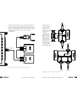
The layout of the wiring connections makes for 
a quick and simple installation. All connections 
on the control's right side are made to boilers, 
pumps, modulating valves and snow melt using 
RJ45 connectors and a Cat5 cable. Once the  
cable is available and tested, it plugs into the 
connector on the control's right side and  
clicks into place to secure the connection.  
(See

 Figure 4-5

.) The connection can easily  

be changed or moved by pressing down on the 
latch and disconnecting from the control. 

The top two ports on the control's right side are 
reserved for boilers. If a second boiler is not part 
of the mechanical system, the second port can  
be used for any other device.

Figure 4-1

Figure 4-4

Figure 4-5

Figure 4-2

Figure 4-3

Summary of Contents for Climate Control-Multifunction

Page 1: ...Uponor Climate Co ntrolTM Multifunction Installation Guide RA DIAN T HEATING SYST EMS CLIMATE CO NTROL MULTIFUNCTION INSTALLATION GUIDE...

Page 2: ...stic Hot Water DHW 3 Zone Pump Control 3 Mixing 3 Snow Melting 3 Semi automatic Control 4 Fully Automatic Control 4 Slab Idle 4 High Temperature 4 Pump Exercising 4 Section 3 Safety Measures 5 Section...

Page 3: ...tion s architecture supports up to eight outputs e g pumps modulating valves boilers The unused ports can support additional zone pumps within the system rather than adding other control elements View...

Page 4: ...ol Multifunction unit monitors the return boiler temperature If the temperature drops too low the system will begin to close the three way valves If this option doesn t work the high temperature pumps...

Page 5: ...set temperature High Temperature If the control supports high temperature control the system will turn on the high temperature pump until the demand call ends However if the minimum boiler return temp...

Page 6: ...following list Installation guide Main control panel Outdoor sensor Supply and return sensor or dual sensor Data key mounted inside display enclosure Important Read the following installation instruc...

Page 7: ...nstalling any additional screws Mark the location with a pencil or pen if anchors are being used See Figure 4 2 6 Install the remaining screws to finish mounting the control Optional Control Panel Mou...

Page 8: ...en active LEDs for the inputs and outputs will turn green On Tx Run Rx Port 1 Input 1 Operate MMI Port 8 Input 8 Port 3 Port 2 Port 4 Port 5 Input 2 Input 3 Input 4 Input 5 Port 6 Input 6 Port 7 Input...

Page 9: ...Control A9012010 for space heating Auto Man A Terminal B Terminal A B Power Space Heating High Temp DHW Typical heating device e g boiler Top View Side View Port 1 Port 8 Port 3 Port 2 Port 4 Port 5 P...

Page 10: ...d snow melting The Climate Co ntrol hydronic controller can connect to any 0 10VAC motor and valve using the Uponor Modulating Valve Control A9063020 Note The motor must be 75 milliamps or less from a...

Page 11: ...maximum of three amps in a variety of applications Common types of uses include primary secondary and domestic hot water DHW pumps As an added feature the Climate Co ntrol Multifunction hydronic contr...

Page 12: ...ite White Red Wire to Pump or Circulator 2 amps Max On Auto Call Pump Relay A9013030 Pump Relay A9013030 Pump Relay A9013030 Off Call On Auto Line Voltage In 115v L N Black Red White or Circulator Wir...

Page 13: ...elt connection with slab sensing Auto Active Remote Push Button optional Top View Side View Port 1 Port 8 Port 3 Port 2 Port 4 Port 5 Port 6 Port 7 Uponor Snow Melt Control A9013051 10K Slab Sensor To...

Page 14: ...d properly on the sheet provided The wiring compartments are enclosed The display is lit and showing the Uponor logo default date and time and outdoor temperature Initial Setup The Display Unit The di...

Page 15: ...path Uponor Screen Settings System Settings Backlight The use of the symbol indicates pressing the OK button The following settings are available Backlighting On Display remains at 100 intensity at al...

Page 16: ...hannel is active If not active 0 0 F displays Supply and Return Temp Display current temperature for the supply and return sensors if the sensors are connected If not connected 0 0 F displays Press or...

Page 17: ...limate Co ntrol Multifunction the most versatile control in mechanical room functionality allows the installer to tell the control which devices are connected and which functions to use If a port has...

Page 18: ...K button The following selections are available DHW Setting Set the requirement for the tank temperature through the tank sensor Demand Input Set the input number for a connection that will start the...

Page 19: ...nformation correctly to match the system then press OK to accept the information SM Snow melt Function The following selections are available SM Channel This sets a reference number This does not corr...

Page 20: ...or ice Outdoor Hi Low Temp This setting indicates the outdoor temperatures all snow melt functions will no longer run SM Delta T This setting indicates the target differential temperature between the...

Page 21: ...Solutions Notes Nothing showing on the display Display appears dark blank No power to control unit Connection issue between control and display Check 24VAC power supply and connection Check cable for...

Page 22: ...55124 USA Tel 800 321 4739 Fax 952 891 1409 Web www uponor usa com Uponor Ltd 655 Park Street Regina SK S4N 5N1 CANADA Tel 888 994 7726 Fax 800 638 9517 Web www uponor ca ClimateCtrl_InsG_1 08 Copyri...

Reviews: