background image

This installation and operation manual describes how to 
install and operate the components of the system.

2.1  Safety instructions

Safety measures

Conform to the following measures when installing and 
operating any Uponor equipment:

• 

Read and follow the instructions in the installation 
and operation manual.

• 

Installation must be performed by a competent 
person in accordance with local regulations.

• 

It is prohibited to make changes or modifications 
not specified in this manual.

• 

All power supply must be switched off before 
starting any wiring work.

• 

Do not use water to clean Uponor components.

• 

Do not expose the Uponor components to 
flammable vapours or gases.

We cannot accept any responsibility for damage 
or breakdown that can result from ignoring these 
instructions.

Power

W

arning

!

The Uponor system uses 50 Hz, 230 V AC 
power. In case of emergency, immediately 
disconnect the power.

Technical constraints

C

aution

!

To avoid interference, keep installation/data 
cables away from power cables of more than 
50 V.

2.2  Correct disposal of this product 

(Waste Electrical and Electronic Equipment)

N OT E !

Applicable in the European Union and other 
European countries with separate collection 
systems

This marking shown on the product or its 

literature indicates that it should not be 
disposed with other household wasted at the 

end of its working life. To prevent possible harm to the 
environment or human health from uncontrolled waste 
disposal, please separate this from other types of wastes 
and recycle it responsibly to promote the sustainable 
reuse of material resources.

Household users should contact either the retailer 
where they purchased this product, or their local 
government office, for details of where and how they 
can take this item for environmentally safe recycling.

Business users should contact their supplier and check 
the terms and conditions of the purchase contract. This 
product should not be mixed with other commercial 
wastes of disposal.

2  Preface

4

U P O N O R   C O M F O R T- E  T H E R M O S TAT   D I G .   P R O G   S E T  T- 8 6   ·   I N S TA L L AT I O N   A N D   O P E R AT I O N   M A N U A L

EN

DK

FI

NO

SE

Summary of Contents for Comfort-E

Page 1: ...08 2017 Uponor Comfort E Thermostat Dig Prog Set T 86 EN INSTALLATION AND O PERATI ON M AN UAL...

Page 2: ...lay 8 5 5 Set the Comfort Levels 8 5 6 Lock the Thermostat 9 5 7 Temperature Control 10 5 8 Temperature Hold 10 5 9 Holiday Mode 10 5 10 Frost Protection 10 5 11 Optional Features 11 6 Troubleshooting...

Page 3: ...d by Uponor is not connected to or used with non Uponor products parts or components except for those approved or specified by Uponor and does not show evidence of tampering mishandling insufficient m...

Page 4: ...ep installation data cables away from power cables of more than 50 V 2 2 Correct disposal of this product Waste Electrical and Electronic Equipment NOTE Applicable in the European Union and other Euro...

Page 5: ...quickly the room cools down Setting a programmable room thermostat to a lower temperature will result in the room being controlled at a lower temperature and saves energy The way to set and use your...

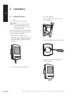
Page 6: ...he thermostat follow these steps 1 Separate the front half of the thermostat from the back plate by placing a small flat head terminal driver into the slots on the bottom face of the thermostat 2 Plac...

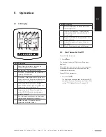
Page 7: ...ed when the thermostat is in holiday mode Pos Description 9 Current Temperature Indicates the current sensor temperature 10 Program Cycle Indicator Displayed during programming only to show which peri...

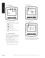
Page 8: ...sor or both The display will clearly show which sensor is being controlled When the thermostat is set to use both sensors the room temperature will be displayed To view the floor temperature follow th...

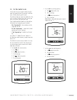
Page 9: ...ge 12 for information on how to change programming modes Feature 12 To schedule time and temperature follow these steps The instruction below is for 5 2 Day Programming It starts by programming the sc...

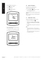
Page 10: ...nlock repeat the step above until the lock symbol disappears Note The keypad lock indicator is only displayed when the lock is active 5 7 Temperature Control To adjust the set temperature follow these...

Page 11: ...tion temperature setting For more information see Feature 03 in section 5 11 Optional Features on page 12 The thermostat will maintain this temperature for the duration of the holiday and will then au...

Page 12: ...t protection mode the flame icon will be displayed 5 11 Optional Features The following settings are optional In most cases they do NOT need to be adjusted Adjust Optional Features To adjust the optio...

Page 13: ...emperature when the thermostat display is turned off As a default this is enabled Feature 04 Frost Protection Temperature This is the temperature maintained when the thermostat is in frost protection...

Page 14: ...0 minutes to raise the building temperature 1 C and starts the heating accordingly On this thermostat optimum start works on the Wake and Return comfort levels Feature 11 Rate of Change Number of minu...

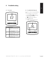
Page 15: ...rrectly or the probe is faulty 6 2 Re calibrate the Thermostat If you need to re calibrate the thermostat follow these steps 1 Press and hold to turn the thermostat OFF 2 Press and hold BOTH and toget...

Page 16: ...urn the thermostat OFF 2 Press and hold and together until the LCD powers up All of the icons will be displayed on screen When the icons have disappeared from the screen the thermostat has been succes...

Page 17: ...l Uponor Comfort E Thermostat Dig Prog Set T 86 Input 230 VAC 50 60 Hz Output 230 VAC 230 VAC 16A MAX IP Rating IP20 7 2 Dimensions 16 51 mm 51 99 42 86 H A 17 UPONOR COMFORT E THERMOSTAT DIG PROG SET...

Page 18: ...ing or Wire Remote Air Sensor Optional RT1 RT2 N N LOAD L Floor Sensor Remote Air Sensor Floor Sensor 230VAC 230 V AC 50 60 Hz 230 V 18 UPO NO R COMFO RT E T HE RMOSTAT D IG PROG S E T T 86 INSTAL L A...

Page 19: ...19 UPONOR COMFORT E THERMOSTAT DIG PROG SET T 86 INSTAL L ATION AND OP ER ATION MAN UAL EN DK FI NO SE...

Page 20: ...AB MRY Virsbo Sweden Uponor Corporation www uponor com Uponor reserves the right to make changes without prior notification to the specification of incorporated components in line with its policy of c...

Reviews: