background image

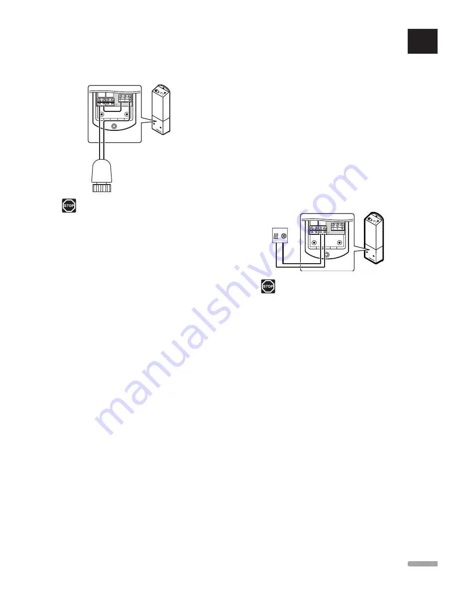
Connect actuator to controller

Connect the actuator to the controller as follows. Use 
the figure below for guidance to the instructions.

230 V

Warning!

Electrical installation and service behind 
secured 230 V AC covers must be carried 
out under the supervision of a qualified 
electrician.

1.  Ensure that the power is disconnected from the 

controller.

2.  Lead the cable from the actuator through the cable 

entry in the bottom of the controller.

3.  Connect the cable from the actuator to 1A (L) and 

N (N) in the controller.

4.  Connect a wire between the free L connection and 

1B in the controller.

The actuator is now installed.

Connect thermostat to controller

The thermostat is connected to the controller through 
wireless radio link.

See also section 6 Uponor Smatrix Wave thermostats 
and sensors for installation of thermostats. 

Connect heating/cooling output to 
controller (optional)

If the system is equipped with a cooling unit (requires 
additional products), the controller can switch between 
heating and cooling by using the heating/cooling 
output.

The heating/cooling output is connected to two-
position relay.

•  When the relay is open, the system is in heating 

mode.

•  When the relay is closed, the system is in cooling 

mode.

To connect a heating/cooling output to the 
controller:

The illustration below shows components of the 
heating/cooling system connected to a relay module.

Warning!

Electrical installation and service behind 
secured 230 V AC covers must be carried 
out under the supervision of a qualified 
electrician.

1.  Ensure that the power is disconnected from both 

the controller and the heating/cooling relay.

2.  Connect the cable to/from the component 

producing heating/cooling to connector 

2A

 and 

2B


on the controller.

Heating/cooling output is now installed.

UK

CZ

DE

DK

EE

ES

FI

FR

HR

HU

IT

LT

LV

NL

NO

PL

PT

RO

RU

SE

SK

1 3

U P O N O R   S M AT R I X   S PA C E / S PA C E   P L U S   ·   I N S TA L L AT I O N   A N D   O P E R AT I O N   M A N U A L

Summary of Contents for smatrix space

Page 1: ...03 2015 Uponor Smatrix Space Space PLUS UK IN STALLATIO N AN D O P ERATION M AN UAL ...

Page 2: ...tion 21 8 2 Normal operation without optional scheduling programs 21 8 3 Operation with scheduling programs 21 8 4 Run mode 21 8 5 Reset the controller 21 8 6 Unregister a thermostat from the controller 21 9 Operate Uponor Smatrix Wave analogue thermostats 22 9 1 Thermostat layout 22 9 2 Adjust temperature 22 9 3 Replace batteries 22 9 4 Factory reset 23 10 Operate Uponor Smatrix Wave digital ther...

Page 3: ... connected to or used with non Uponor products parts or components except for those approved or specified by Uponor and does not show evidence of tampering mishandling insufficient maintenance improper storage neglect or accidental damage before installation and being put into operation While Uponor has made efforts to ensure that the manual is accurate Uponor does not guarantee or warrant the acc...

Page 4: ... and the chances of interference from other radio sources are very low However in some rare cases it might not be possible to establish perfect radio communication The transmission range is sufficient for most applications but each building has different obstacles affecting radio communication and maximum transmission distance If communication difficulties exist Uponor recommends relocating the co...

Page 5: ...T 168 Uponor Smatrix Space PLUS Renovation Heating and cooling without a relative humidity sensor with an optional external sensor digital thermostat T 166 Uponor Smatrix Space Renovation Basic heating standard thermostat T 165 3 2 Example of a system The illustration below shows an example of an Uponor Smatrix Space Cooling installation A B C D Item Description A Uponor Smatrix Space Controller X...

Page 6: ...e actuator 230 V 2 way communication with a room thermostat Heating cooling relay Basic relative humidity control Lower indoor temperature with night set back Options Free placement and orientation when installing the controller Components of the controller The illustration below shows the controller and its components B A Item Description A Uponor Smatrix Space Controller X 161 power cable not in...

Page 7: ... Temperature settings are adjusted using the buttons on the front Main characteristics Backlit display dims after 10 seconds of inactivity Displays Celsius or Fahrenheit Heating cooling demand as well as low battery indication in display Displays software version during power up sequence Setpoint range is 5 35 C Room temperature regulation with use of optional external temperature sensors Displays...

Page 8: ...ting Relative humidity limit indicated in display Scheduling pre programmed and customizable schedules Lower indoor temperature with night set back Can be placed up to 30 meters away from the controller Components of the thermostat The illustration below shows the thermostat and its components A E C B D F Item Description A Uponor Smatrix Wave Thermostat Prog RH T 168 B Wall bracket C Stand D Batt...

Page 9: ...ature for best performance of the system It is used for high control accuracy by deciding when to start and stop heating and cooling based on information from the sensor and setpoint value Heating fall back If the connection to the thermostat is lost the loop cannot be regulated using the air temperature The controller then activates a fall back function and the actuator is operated with a set int...

Page 10: ...onents Check whether an external temperature sensor is to be installed with a compatible thermostat Study the wiring diagram in the end of this manual To determine where to best place the Uponor Smatrix Space components follow these guidelines Ensure that the controller can be installed close to the valve acutator Note that each actuator must have its own controller Ensure that the controller can ...

Page 11: ...ostat controls the actuator regulating the room temperature using the setpoint value offset temperatures and scheduling T 168 only A signal is sent to an external heating cooling product third party product just schematic example in illustration such as a 3 way switch over valve Option T 166 or T 168 only External temperature sensor Floor temperature sensor Schedules T 168 only Programmable schedu...

Page 12: ...in a kit including screws and wall plugs Screws and wall plugs The figure below shows controller mounting hole positions and how to attach it to the wall using screws and wall plugs 162 mm 5 3 Connect components to controller Refer to the wiring diagram found in the end of this document The illustration below shows the inside of the controller A F G H D E B C Item Description A Uponor Smatrix Spac...

Page 13: ...ut to controller optional If the system is equipped with a cooling unit requires additional products the controller can switch between heating and cooling by using the heating cooling output The heating cooling output is connected to two position relay When the relay is open the system is in heating mode When the relay is closed the system is in cooling mode To connect a heating cooling output to ...

Page 14: ... actuators The controller manages the temperature setpoint When a temperature change occurs the actuator opens or closes the valve to adjust the room temperature To test the actuators 1 Increase the setpoint on the thermostat to the maximum setting The acutator should start opening and the LED for relay 1 on the controller lights up wait until fully opened 2 Decrease the setpoint on the thermostat...

Page 15: ...systems for example 1 2 3 etc If the thermostat can connect to an external sensor add information about sensor type when applicable Available thermostat and sensor combinations Room temperature Room and floor temperature Room and outdoor temperature Remote sensor temperature 6 3 Insert batteries All thermostats use two alkaline 1 5 V AAA batteries which provides about 2 years of battery life as lo...

Page 16: ...Attach a thermostat to the wall The thermostats are delivered in kits including screws wall plugs and a wall bracket presenting several options of attaching the thermostat to the wall Using wall bracket recommended The illustration below shows thermostat mounting hole positions and how to attach it to the wall using a wall bracket 2 1 3 60 mm Screw and wall plug The illustration below shows how to...

Page 17: ...ware requires the time and date to be set Use buttons or to change the value press the OK button to set the value and move to the next editable value NOTE If no button is pressed for about 8 seconds the current values will be saved and the software exits to control mode 1 Set hours 2 Set minutes 3 Set 12 h or 24 h display of time 4 Set day of the week 1 Monday 7 Sunday 5 Set day of the month 6 Set...

Page 18: ...RFT Room temperature with external floor sensor RS Remote sensor RO Room temperature with remote outdoor sensor For display of outdoor temperature only 5 Press and hold the OK button for about 3 seconds to exit the settings menu Temperature setpoint The thermostats are delivered with a default setpoint of 21 C may differ depending on heating mode The illustration below shows how to adjust the ther...

Page 19: ...ntly press and hold the registration button on the thermostat release when the LED on the front of the thermostat starts flashing The LED on the controller starts flashing fast to turn off a few seconds later Thermostats T 166 and T 168 2 1 Press and hold both and buttons on the thermostat until the text CnF configure and a communication icon is displayed The LED on the controller starts flashing ...

Page 20: ...ng 2 Reset the thermostat to the defined operating settings 3 Close the cover of the controller 4 Attach the thermostat to the wall 5 Print and fill in the Installation report located at the end of the manual 6 Give the manual and all information about the system to the user 2 1 1 4 3 5 6 UK CZ DE DK EE ES FI FR HR HU IT LT LV NL NO PL PT RO RU SE SK 20 UPONOR S MATR IX SPACE S PACE P LUS IN STALL...

Page 21: ...ital thermostat 8 3 Operation with scheduling programs Scheduling programs provide an option to switch the zone between Comfort and ECO mode using a 7 day program This optimises the installation and conserves energy The use of scheduling programs requires Uponor Smatrix Wave Thermostat Prog RH T 168 For information about operating the thermostat see section 10 Operating Uponor Smatrix Wave digital...

Page 22: ...at to adjust the temperature A backlight will light up when twisting the dial It dims out after about 10 seconds of inactivity The illustration below shows how to adjust the thermostat temperature setpoint To adjust the thermostat temperature setpoint Twist the dial clockwise for a higher temperature Twist the dial counter clockwise for a lower temperature 9 3 Replace batteries Replace the batteri...

Page 23: ...logue thermostat 1 Angle the thermostat from the bracket 2 Remove it from the wall 3 Gently press and hold the registration button on the thermostat release when the demand LED starts flashing 4 Change the Disable timer switch twice regardless of starting position 5 The thermostat is now reset to factory default UK CZ DE DK EE ES FI FR HR HU IT LT LV NL NO PL PT RO RU SE SK 23 UPO N O R S M AT RIX...

Page 24: ...es 10 2 Display layout The figure below shows all possible symbols and characters that can be shown on the display A E B C D F H I G T 166 L C B D F E G K J I H A T 168 Pos Icon Description A T 166 only Message field using three alphanumerical characters T 166 T 168 Temperature reading using a or sign two digital characters a decimal point and a character showing either 0 or 5 T 168 only Relative ...

Page 25: ...selected or scheduled hour indicators for Comfort mode between 0 00 and 24 00 Half 30 minutes Full 1 hour 10 3 Operating buttons The figure below shows buttons used to operate the digital thermostats B C A Pos Description A The and buttons are used to Adjust setpoint temperature Modify parameters in the settings menus B C The OK button is used to Toggle between current status data and values of av...

Page 26: ...s changed by adjusting the setpoint on the thermostat Use the buttons on the thermostat to adjust the temperature The display will light up when pushing a button It shuts off after about 10 seconds of inactivity The illustration below shows how to adjust the thermostat temperature setpoint To adjust the thermostat temperature setpoint of the current control mode 1 Press the or button once The scre...

Page 27: ...displayed in the top right corner of the display 3 Use buttons or to change the numbers to 04 and press OK 4 Current control mode is displayed RT RFT RS or RO 5 Use buttons or to change control mode see list below and press OK RT Room temperature RFT Room temperature with external floor sensor RS Remote sensor RO Room temperature with remote outdoor sensor For display of outdoor temperature only P...

Page 28: ...e setback temperature Program P1 Program P2 Program P3 Program P4 Program P5 Program P6 To change this setting 1 Press OK and the parameter starts flashing 2 Use buttons or to select program Select between P1 P6 U and Off Program U 2 1 The current day starts flashing Decide to program a schedule in one of two ways Single day Program only a single day Full week Program every day ir the week UK CZ D...

Page 29: ...owing day 2 1 5 Repeat steps 2 1 2 through 2 1 4 until all available days are programmed 2 1 6 Press OK to confirm the change and return to the settings menu 02 Heating cooling changeover In this menu it is manually set whether the system is in heating or cooling mode To change this setting 1 Press OK and the parameter starts flashing 2 Use buttons or to change the setting see list below H Heating...

Page 30: ...enu a limit on the minimum allowable floor temperature is set This menu is only visible if control mode RFT is activated in settings menu 04 To change this setting 1 Press OK and the parameter starts flashing 2 Use buttons or to change the parameter Default 20 C Setting range 10 30 C 0 5 C increments NOTE If this parameter is set lower than 16 C the cooling icon will start flashing warning for ris...

Page 31: ...next editable value To change this setting 1 Press OK and the parameter starts flashing 2 Set hours 3 Set minutes 4 Set 12 h or 24 h display of time 5 Set day of the week 1 Monday 7 Sunday 6 Set day of the month 7 Set month 8 Set year 9 Press OK to confirm change and return to the settings menu 10 10 Factory reset Factory reset sets all parameter values to default settings NOTE Do not factory rese...

Page 32: ...shes when there is radio activity i e when the relays are controlled or when the thermostat sends data and shuts off after a few seconds The illustration below shows the position of the controller LEDs B C A Item Description A LED relay 1 activity B LED relay 2 activity C LED radio connection The table below describes the status of the controller LEDs LED Status Relay 1 Red on Heating mode actuato...

Page 33: ...re displayed on the thermostat changes after the thermostat is moved The thermostat may be influenced by an external heat source Change location of the thermostat White indicator cannot be seen in window of the actuator The actuator does not open Replace the actuator Contact the installer ECO icon in thermostat display T 168 only ECO mode Change ECO profile or assign another profile to the room Re...

Page 34: ...nstalled upside down reverse polarity Install the batteries correctly Radio transmission icon is displayed but the signals are received only when the thermostat is close to the antenna Transmitter working with reduced signal intensity Force the thermostat to transmit by changing the temperature setpoint Replace thermostat New installations in building shield radio signals for example metal door sa...

Page 35: ...following information before contacting an installer Installation report Drawings of the underfloor heating system if available List of all alarms including time and date 12 6 Installer instructions To determine if a problem is caused by the supply system or the control system loosen the actuator from the manifold for the room concerned wait a few minutes and check if the flow pipe of the underflo...

Page 36: ... 0 C to 50 C Storage temperature 20 C to 70 C Maximum consumption 2 W Relay outputs 230 V AC 10 15 250 V AC 8 A maximum Power connection 1 m cable with europlug except UK Connection terminals Up to 4 0 mm solid or 2 5 mm flexible with ferrules EN 60730 1 Automatic electrical controls for household and similar use Part 1 General requirements EN 60730 2 1 Automatic electrical controls for household ...

Page 37: ...lay 2 connector heating cooling output H Power connector 230 V AC 50 Hz 13 4 Wiring diagrams Uponor Smatrix Space 230 V L 230 V AC 50 Hz N 13 5 Dimensions Controller 50 mm 25 mm 162 mm 153 mm 171 mm Thermostats T 166 T 168 80 mm 60 mm 80 mm 26 5 mm T 165 80 mm 60 mm 80 mm 26 5 mm UK CZ DE DK EE ES FI FR HR HU IT LT LV NL NO PL PT RO RU SE SK 37 UPO N O R S M AT RIX SPACE SPAC E PLUS INSTALLATI ON ...

Page 38: ...165 230 V Controller Thermostat Rooms Thermostat Floor sensor Remote sensor Heating cooling Yes No UK CZ DE DK EE ES FI FR HR HU IT LT LV NL NO PL PT RO RU SE SK 38 UPONOR S MATR IX SPACE S PACE P LUS IN STALL ATION AN D OPE R ATION MANUAL ...

Page 39: ...UK CZ DE DK EE ES FI FR HR HU IT LT LV NL NO PL PT RO RU SE SK 39 UPO N O R S M AT RIX SPACE SPAC E PLUS INSTALLATI ON AND OPE RATION MANUAL ...

Page 40: ...or AB Virsbo Sweden Uponor Corporation www uponor com Uponor reserves the right to make changes without prior notification to the specification of incorporated components in line with its policy of continuous improvement and development ...

Reviews: