background image

INTRODUCTION

VIEWING THE STATUS OF 
THE SYSTEM PERFORMANCE  

• The View Menu is available for viewing the current status of

the system performance

• By selecting the View Menu, and then pushing the item

button, you can scroll through the available menu items
showing the current settings and temperatures in the system

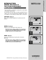
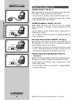
OUTDOOR

(See fig. a)

Shows actual outside temperature at outdoor sensor S4
location

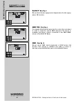
SLAB TRG

(See fig. b)

The targeted temperature the control has calculated in order
to meet current conditions

SLAB

(See fig. c)

Shows actual slab temperature at slab sensor S7 location

STATUS

(See fig. d)

Shows current snow melt operating status. See Control
Function Overview section page 72 for more detailed
information.

Snow Melt Mode

10

INTRODUCTION

INTRODUCTION - Viewing the Status of the System Performance

%

View

o

F

1

a

%

View

o

F

1

b

%

View

o

F

1

c

%

View

1

hr

d

Access Level

LTD

USER

INST

ADV

Access Level

LTD

USER

INST

ADV

Access Level

LTD

USER

INST

ADV

Access Level

LTD

USER

INST

ADV

Summary of Contents for SYSTEMpro 311

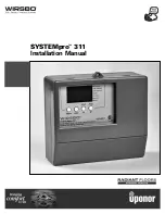
Page 1: ...SYSTEMpro 311 Installation Manual...

Page 2: ...lation Manual is published by Uponor Wirsbo 5925 148th Street West Apple Valley MN 55124 952 891 2000 2002 Uponor Wirsbo All rights reserved First Edition First Printing July 2002 Printed in the Unite...

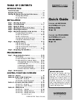
Page 3: ...High Temp Zone Settings 38 41 B DHW Settings 42 43 C Mixing Device Settings 44 49 D Snow Melting Settings 50 53 E Boiler Operation Settings 54 55 Step 2 Test Sequence 56 57 CONTROL FUNCTION OVERVIEW...

Page 4: ...9 Section F Boiler Operation 80 81 Section F1 Boiler Supply Sensor 80 81 Section G Troubleshooting 82 83 APPENDIX I Variable Speed Injection Mixing 85 87 II SYSTEMpro 311 Menu Tree 88 89 III Applicati...

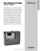
Page 5: ...It can be used to supply mixed loop water temperature heat to a radiant floor or snowmelt application and is specifically created to operate efficiently as part of a Wirsbo radiant snow melt heating s...

Page 6: ...splay To view the next available item press and release the Item button Once you have reached the last available item in a menu press and release the Item button to return the display to the first ite...

Page 7: ...the selected item Display Symbol Description o o Open Close Displays when the actuator is opening or closing Mixing Device Output Scale Shows output of injection pump or mixing valve Arrows show whet...

Page 8: ...the normal set up of the control NOTE This is how the control arrives from the factory 4 Advanced ADV See fig d Allows access to all of the control settings available How to Set The Access Level ACCES...

Page 9: ...room temperature for the mixing zone NOTE This screen will be available in the View Menu only when the Indoor INDR sensor is selected under the MIX 10K screen in the ADJUST Menu ROOM See fig c Actual...

Page 10: ...er to meet current conditions MIX SUP See fig f Shows actual mix supply water temperature to the system at mix supply sensor S1 location Boil TRG See fig g The targeted boiler supply temperature the c...

Page 11: ...DHW device is selected in the DHW THRU screen in the ADJUST Menu DHW See fig j Shows the actual DHW tank temperature at the DHW sensor S6 location NOTE This screen will be available in the View Menu...

Page 12: ...cation SLAB TRG See fig b The targeted temperature the control has calculated in order to meet current conditions SLAB See fig c Shows actual slab temperature at slab sensor S7 location STATUS See fig...

Page 13: ...rature differential Delta T between mix supply sensor S1 and mix return sensor S5 locations Boil TRG See fig h The targeted boiler supply temperature the control has calculated in order to meet the cu...

Page 14: ...y when a sensor is selected in the DHW SENS screen in the ADJUST Menu DHW See fig k Shows actual DHW tank temperature at DHW sensor S6 location This screen is available only when a sensor is selected...

Page 15: ...Electrical Connections to the Control 23 28 Powered Input Connection 23 Output Connections 24 25 Sensor Connections 26 Unpowered Input Connections 27 Temperature Resistance Chart 28 Step 7 Testing the...

Page 16: ...AND DISCLAIMERS Failure to install and or operate this control properly could result in Damage to the equipment Personal injury Property damage It is up to you to make sure this control is installed...

Page 17: ...top of the front cover and pull out and down See fig a Lift the front cover up and away from the control See fig b Loosen the screws at the front of the wiring cover See fig c The wiring cover pulls...

Page 18: ...de the control upwards See fig f The control lifts up and away from the base See fig g Mounting the Base See fig h 1 Find a convenient and accessible location typically in the mechanical room 2 Follow...

Page 19: ...N rail This will be a popular option for those who prefer to mount the control inside a larger electrical panel The wiring can enter the bottom or the back of the enclosure Knock outs provided in the...

Page 20: ...Components 1 Install the various sensors indicated below as per instructions listed and run the wiring back to the control base and label all wires for later installation Main Sensors Outdoor Sensor S...

Page 21: ...HE CONTROL TO THE BASE 1 Push the SYSTEMpro 311 control into the base you mounted in Step 2 2 Slide the control down until it snaps firmly into place See fig a 19 INSTALLATION INSTALLATION Step 4 Atta...

Page 22: ...sources such as solar gain exhaust ventilation or window openings The outdoor sensor should be installed at an elevation above the ground that will prevent accidental damage or tampering Installing th...

Page 23: ...similar fitting Proper sensor location requires that the fluid is thoroughly mixed within the pipe before it reaches the sensor Step Two Wiring and Testing CAUTION Do not run sensor wires parallel to...

Page 24: ...e if required See fig j Step Two Wiring and testing CAUTION Do not run sensor wires parallel to telephone or power cables If the sensor wires are located in an area with strong sources of electromagne...

Page 25: ...OTE When connecting a Wirsbo Thermostat WT1 or WT2 directly to the Mix Demand Terminals 1 and 2 a 0 5 watt 1000 ohm resistor needs to be installed parallel as shown A packet with the resistor and sche...

Page 26: ...utput terminal 8 is a powered output When relay in the SystemPro 311 closes 120 VAC is provided to Boil P3 terminal 8 from Power L terminal 7 To operate primary pump connect one side of primary pump c...

Page 27: ...onnect other wire on variable speed injection pump to live L side of 120 VAC power supply Connect Pwr Mix terminal 17 to neutral N side of 120 VAC power source 7 Mixing Valve Actuator See fig k If a m...

Page 28: ...eturn Sensor S5 wire to Com and Ret S5 terminals 20 and 22 See fig o Measures fluid return temperature from snow melting slab NOTE This sensor is only used when the Snow Melting Mixing Reset DIP switc...

Page 29: ...rminal on zone control to Com terminal 24 on the SYSTEMpro 311 Connect the ZoOut terminal on zone control to Boil ZoIn terminal 25 on the SYSTEMpro 311 16 tN2 Device See fig t A Remote Display Module...

Page 30: ...710 336 606 280 279 234 196 196 358 165 180 139 402 118 018 100 221 85 362 72 918 62 465 53 658 46 218 39 913 34 558 29 996 26 099 22 763 19 900 17 436 15 311 13 474 11 883 10 501 9 299 8 250 7 334 6...

Page 31: ...red to measure the sensor resistance In addition to this the actual temperature must be measured with either a good quality digital thermometer or if a thermometer is not available a second sensor can...

Page 32: ...d terminals 1 and 2 Boiler Demand if used Measure voltage between Boil Dem and Com Dem terminals 3 and 4 DHW Demand if used Measure voltage between DHW Dem and Com Dem terminals 4 and 5 Test the Outpu...

Page 33: ...uld turn on or the DHW valve should open completely Boiler connected to the Boiler terminals 15 and 16 See fig e Make sure power to the boiler circuit is off Install a jumper between the terminals 15...

Page 34: ...g to STEP 2 STEP 2 See fig h Install a jumper between the Pwr Mix and Cls P4 terminals 17 and 19 Power up circuit actuator should move in closing direction If motor closes correctly turn off power to...

Page 35: ...e control 3 Push the terminal blocks into the headers they should snap firmly into place See fig a 4 Install supplied safety dividers between unpowered sensor inputs and powered or 120 VAC wiring cham...

Page 36: ...ogramming the Misc Menu 37 Programming the Adjust Menu 38 55 A Boiler High Temp Zone Settings 38 41 B DHW Settings 42 43 C Mixing Device Settings 44 49 D Snow Melting Settings 50 53 E Boiler Operation...

Page 37: ...what items are available to be viewed and controlled through the User Interface 2 REVIEW The Control Function Overview if you are not familiar with how the control functions operate in conjunction wit...

Page 38: ...ch from unlocked position to the locked position As long as the DIP switch is in the locked position the access level of the control can no longer be viewed or adjusted in its Miscellaneous Misc Menu...

Page 39: ...ntrol automatically returns to the default display RANGE OFF 90 sec ON DEFAULT ON ACCESS See fig c 1 Go to ACCESS item field in Miscellaneous MISC Menu 2 Select the level of access that you wish to be...

Page 40: ...PROGRAMMING THE ADJUST MENU A BOILER HIGH TEMP ZONE SETTINGS 38 PROGRAMMING PROGRAMMING Step 1 Programming the Control...

Page 41: ...temp zones RANGE 35 to 100 F 2 to 38 C DEFAULT 70 F 21 C NOTE There is only a 3 F 1 C adjustment in the LTD Access Level BOILER INDOOR Boil INDR See fig c 1 Go to Boil INDR item field in Adjust Menu...

Page 42: ...ler manufacturer s literature RANGE 120 to 225 F OFF 49 to 107 C OFF DEFAULT 210 F 99 C BOILER MINIMUM Boil MIN See fig f 1 Go to Boil MIN item field in Adjust Menu 2 Set to the lowest water temperatu...

Page 43: ...The control enters into WWSD when slab and outdoor temperatures exceed MELTING temperature by more than 1 5 F 1 C 1 Go to WWSD item field in the Adjust Menu 2 Set to an outdoor temperature at which th...

Page 44: ...PROGRAMMING THE ADJUST MENU B DHW SETTINGS 42 PROGRAMMING PROGRAMMING Step 1 Programming the Control...

Page 45: ...DHW storage tank temperature RANGE OFF 70 to 190 F OFF 21 to 88 C DEFAULT 140 F 60 C NOTE If DHW THRU is set to NONE this menu will not be available NOTE DHW TANK should only be selected if a universa...

Page 46: ...PROGRAMMING THE ADJUST MENU DIP set to Mixing Reset C MIXING DEVICE SETTINGS 44 PROGRAMMING PROGRAMMING Step 1 Programming the Control...

Page 47: ...10K INDOOR SENSOR MIX 10K See fig m 1 Go to MIX 10K item field in Adjust Menu 2 To add an indoor sensor for temperature control of a single zone mixing system set to INDR 3 To add indoor temperature...

Page 48: ...ig o 1 Go to MIX 10K item field in Adjust Menu 2 Set MIX 10K to SLAB 3 Go to SLAB MAX item field in Adjust Menu 4 Set the maximum allowed core temperature of slab NOTE If slab is to be maintained at a...

Page 49: ...2 to 38 C DEFAULT 70 F 21 C MIXING DESIGN MIX DSGN See fig r 1 Go to MIX DSGN item field in Adjust Menu 2 Set to the design supply water temperature calculated in heat loss calculation for the mixing...

Page 50: ...heat loss calculation RANGE 60 to 50 F 51 to 10 C DEFAULT 10 F 12 C MIXING DEVICE SELECTION MIXING See fig u 1 Go to MIXING item field in Adjust Menu 2 Set the type of mixing device used floating acti...

Page 51: ...ATHER SHUT DOWN WWSD See fig w The control enters into WWSD when slab and outdoor temperatures exceed MELTING temperature by more than 1 5 F 1 C 1 Go to WWSD item field in the Adjust Menu 2 Set to an...

Page 52: ...PROGRAMMING THE ADJUST MENU D SNOW MELTING SETTINGS 50 PROGRAMMING PROGRAMMING Step 1 Programming the Control...

Page 53: ...as reached melting temperature 1 Go to RUN TIME item field in Adjust Menu 2 Set the time in which slab is to be operated at Melting temperature during a melting demand RANGE 0 30 to 17 00 hr INF Infin...

Page 54: ...sensor for temperature control for snow melting set to SLAB RANGE NONE SLAB DEFAULT NONE MIXING MAXIMUM MIX MAX See fig dd 1 Go to MIX MAX item field in Adjust Menu 2 Set to highest water temperature...

Page 55: ...OT 3 Go to MOTR SPD item field in Adjust Menu 4 Set the time the actuating motor requires to operate from fully closed to fully open RANGE 30 to 230 sec DEFAULT 150 sec WARM WEATHER SHUT DOWN WWSD See...

Page 56: ...PROGRAMMING THE ADJUST MENU E BOILER OPERATION 54 PROGRAMMING PROGRAMMING Step 1 Programming the Control...

Page 57: ...with a differential to prevent short cycling With the SYSTEMpro 311 it has either a fixed or automatic differential setting that may be selected 1 Go to Boil DIFF item field in Adjust Menu 2 Select A...

Page 58: ...advance through the test sequence To reach the desired step repeatedly press and release the Test button until the appropriate device and segment in the display turn on Step 1 If FLOT is selected in M...

Page 59: ...to the maximum set temperatures and the mixing device at the set percentage as long as there is a demand for heat This mode may be used for running all circulators during system start up in order to...

Page 60: ...Section E1 General 72 75 Section E2 With Slab Sensor 76 77 Section E3 Without Slab Sensor 77 78 Section E4 Snow Melt Enable 78 79 Section F Boiler Operation 80 81 Section F1 Boiler Supply Sensor 80 8...

Page 61: ...rates as described in Section C EXERCISING The SYSTEMpro 311 has a built in pump and valve exercising function If a pump or valve output on the control has not been operated at least once during every...

Page 62: ...il MIN See fig c The Boil MIN is the lowest water temperature that the control is allowed to use as a boiler target temperature Refer to the boiler manufacturer s literature During mild conditions if...

Page 63: ...s The control will respond to a DHW demand and operates as described in Section C BOILER INDOOR Boil INDR See fig f Boil INDR is the room temperature used in original building heat loss calculations S...

Page 64: ...Pmp P7 contact which starts the boiler system pump The control turns on the primary pump and boiler system pump segments in the LCD The control calculates a Boil TRG supply temperature then fires the...

Page 65: ...s for a DHW sensor connected to the DHW S6 and the Com terminals 27 and 28 The DHW TANK setting is used to set the desired indirect DHW tank temperature When the temperature at the DHW sensor drops 3...

Page 66: ...using a primary loop with DHW tank piped in primary secondary select DHW valve BOILER TARGET DURING DHW GENERATION Boil TRG See fig d The Boil TRG temperature during DHW operation depends on whether...

Page 67: ...o operate without change DHW PRIORITY OVERRIDE To prevent the building from cooling off too much or from a potential freeze up during DHW priority the control limits the amount of time for DHW priorit...

Page 68: ...ply temperature drops below current Boil TRG temperature DHW MIXING PURGE After DHW operation the boiler is extremely hot while heating zones may have cooled off considerably after being off for a per...

Page 69: ...d MIX SUP temperature is near MIX MAX temperature the LCD s Maximum pointer turns on while either the MIX TRG temperature or the MIX SUP temperature is viewed WARM WEATHER SHUT DOWN WWSD See fig d Whe...

Page 70: ...l to the original MIX TRG NOTE This step minimizes overheating the zone while control is operating at MIX MIN temperature MIXING ROOM MIX ROOM See fig g MIX ROOM is desired room temperature for mixing...

Page 71: ...erature to part of the heating system by varying the speed of an injection pump or modulating a mixing valve This selection is made under the MIXING item in the Adjust Menu VARIABLE SPEED INJECTION VA...

Page 72: ...LCD Control calculates a MIX TRG temperature based on outdoor air temperature and settings If required control operates Boiler contact as described in Section B2 page 62 to provide heat to mixing devi...

Page 73: ...ontrol the actual slab temperature Slab sensor is placed in the slab and connected to Com and Mix 10K terminals 20 and 21 With slab sensor connected the control will limit the mixing supply temperatur...

Page 74: ...eat is transferred to snow melting system and to protect slab from thermal stress damage The control limits the rate at which heat is applied to slab through T MAX setting T delta T is the temperature...

Page 75: ...ed STATUS It displays current operating status of snow melting system STRT See fig c Displayed after snow melting system has been enabled and remains on until slab reaches melting temperature If the s...

Page 76: ...g mode WWSD See fig i Displayed when control is in a Warm Weather Shut Down CWCO See fig j Displayed when control is in a Cold Weather Cut Out 74 CONTROL FUNCTION OVERVIEW CONTROL FUNCTION OVERVIEW CO...

Page 77: ...ts to take place until the outdoor temperature rises above the CWCO setting When the control is already in melting mode the CWCO only occurs when the outdoor temperature is less than CWCO setting and...

Page 78: ...cribed in section E4 must be used The MELTING setting in the Adjust Menu sets slab surface temperature that is maintained while control is in melting mode NOTE When control is in melting mode Melting...

Page 79: ...freeze over WARM WEATHER SHUT DOWN WWSD See fig p When a slab sensor is not in use The Warm Weather Shut Down is determined only from the outdoor temperature If outdoor temperature rises above MELTIN...

Page 80: ...d Snow Melt Enable Module Remote Display Module Using Start Stop buttons on the SYSTEMpro 311 EXTERNAL MIX DEMAND An external snow melting demand is generated when a voltage between 24 and 240 VAC is...

Page 81: ...the word STRT is displayed in the LCD for at least 5 seconds The Remote Display Module then displays RUN TIME setting to allow user to adjust it To disable snow melting system when it is in melting mo...

Page 82: ...ld conditions if the control calculates a Boil TRG temperature below Boil MIN setting Boil TRG temperature is adjusted to at least the Boil MIN setting In this mode if boiler is operating and boiler s...

Page 83: ...rol automatically adjusts boiler differential setting under current load conditions to minimize short cycling BOILER OPERATION When the SYSTEMpro 311 notices that boiler operation is required Boiler c...

Page 84: ...ttent For how long has the problem existed This information is critical in correctly diagnosing the problem Understand the sequence of operation of the system If a particular zone is not receiving eno...

Page 85: ...ing as indicated by the LCD This information is an essential step if additional assistance is required to diagnose the problem Isolate the problem between the control and the system Now that the seque...

Page 86: ...Variable Speed Injection Mixing 85 87 II SYSTEMpro 311 Menu Tree 88 89 III Application Drawings 90 97 IV Error Message Overview 98 101 V SYSTEMpro 311 Program Setup 102 103 NOTES 84 APPENDIX APPENDIX...

Page 87: ...device is required To achieve the lower water temperature required for the radiant system the high temperature boiler water must be blended or injected into the return side of the radiant system to a...

Page 88: ...on See fig b FV Flow Rate Injection Loop in GPM F1 Radiant Secondary Loop Flow Rate in GPM T1 Boiler Primary Loop Supply Temperature T2 Radiant Secondary Loop Supply Temperature TR Radiant Secondary L...

Page 89: ...2 Note 1 Note 2 To LOW Temperature Heating System d Injection into a vertical loop System Pump Balancing Valve Variable Speed Injection Pump Primary Pump From HIGH Temperature Loop Note 1 Note 3 Note...

Page 90: ...88 APPENDIX II APPENDIX II SYSTEMpro 311 Menu Tree...

Page 91: ...89 APPENDIX II APPENDIX II SYSTEMpro 311 Menu Tree...

Page 92: ...90 APPENDIX III APPENDIX III Application Drawings...

Page 93: ...91 APPENDIX III APPENDIX III Application Drawings...

Page 94: ...92 APPENDIX III APPENDIX III Application Drawings...

Page 95: ...93 APPENDIX III APPENDIX III Application Drawings...

Page 96: ...94 APPENDIX III APPENDIX III Application Drawings...

Page 97: ...95 APPENDIX III APPENDIX III Application Drawings...

Page 98: ...96 APPENDIX III APPENDIX III Application Drawings...

Page 99: ...97 APPENDIX III APPENDIX III Application Drawings...

Page 100: ...fig b NOTE Access level must be set to ADV in order to clear the error The control was unable to read a piece of information stored in the Miscellaneous Menu Because of this the control was required t...

Page 101: ...operation Locate and repair the problem as described in Installation Step 7 page 29 To clear the error message from the control after the sensor has been repaired press either the Menu or Item button...

Page 102: ...the Boil MIN is set lower than 100 F 38 C the control does not operate the Boiler contact Locate and repair the problem as described in Installation Step 7 page 29 To clear the error message from the...

Page 103: ...f nothing is connected to the Boil ZoIn input Locate and repair the problem as described in Installation Step 7 page 29 To clear the error message from the control after the problem has been corrected...

Page 104: ...___DHW DHW TANK set tank temp or OFF _____OFF _____ F DHW PRI select MIX if you want priority over heating _____NONE _____MIX MIXING DEVICE SETTINGS MIX ROOM room temp for Mixing zones _____ F MIX 10K...

Page 105: ...elting mode time INF or OFF _____OFF _____hr min _____INF T MAX max differential between supply return or OFF _____OFF _____ F CWCO Cold Weather Cut Off or OFF _____OFF _____ F BOILER OPERATION Boil M...

Page 106: ......

Page 107: ...SYSTEMpro 311 Installation Manual Uponor Wirsbo 5925 148th STREET WEST APPLE VALLEY MN 55124 TEL 800 321 4739 FAX 952 891 1409 www wirsbo com Copyright 2002 Uponor Wirsbo Printed in the United States...

Reviews: