background image

5.5 Treatment plant pH 
adjustment

A low pH in the treatment plant 
process tank may result in a 
decrease in sludge particle size, 
which infl uences sludge behaviour 
in the sludge bag. However, the 
treatment results are not directly 
infl uenced by the pH value.

The simplest way to adjust the 
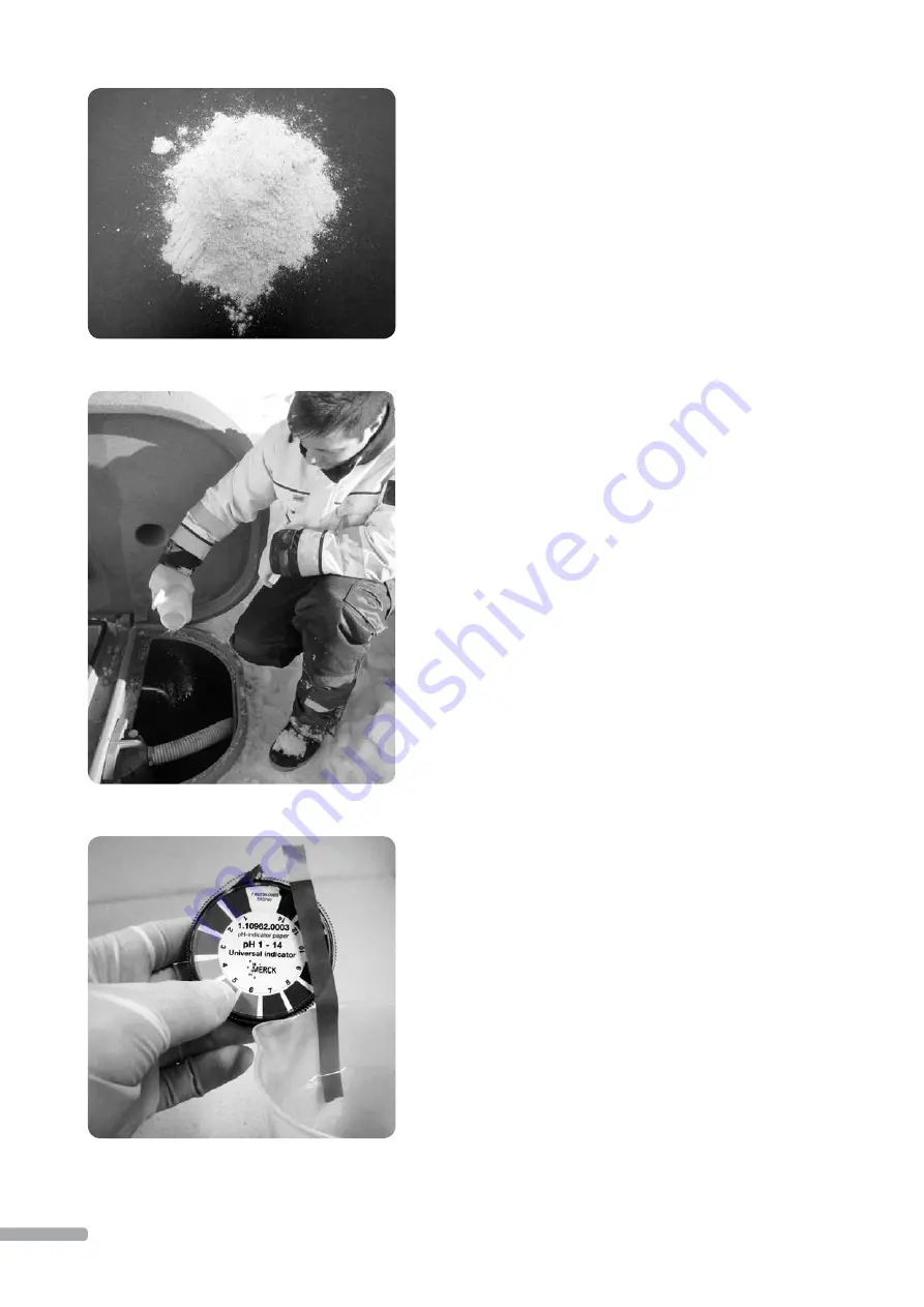
treatment plant pH is by liming. 
The pH adjustment is recommend-
ed if the pH value in the treatment 
plant is below 6. 

If the household water pH is low, 
so is the treatment plant pH. Well 
water should be examined accord-
ing to recommendations at least 
every three years.

5.5.1 Lime type

The correct type of lime for the 
treatment plant is lime ground 
from limestone crush. Limestone 
crush is used in agriculture and as 
garden fertilizer. The lime should 
be as fi ne as possible for it to have 
an effi

  cient eff ect. The pH can also 

be adjusted with sodium (sodium 
hydroxide).

Hydrated lime must not be 
added into the treatment plant 
as it is a strong alkali that may 
lead to active sludge death.


Picture 42

Picture 43

Picture 44

5.5.2 Dosing and monitoring

Lime is added into the treatment 
plant’s process tank (picture 43). 
Aeration should be on in the pro-
cess tank at the time of liming so 
that the lime dissolves as effi

  ciently 

as possible. If the process tank is 
not bubbling at the time of liming, 
the compressor plug can be tem-
porarily moved to the X6 service 
socket to start the aeration process 
immediately. The plug must be put 
back to its own place aft er liming. 
Lime will raise the pH to neutral 
(pH 7). There is no risk of overdos-
ing with the correct lime type. In 
the beginning, it is recommended 
to add 2dl of lime 2 to 3 times per 
week. The dosage amount depends 
on the treatment plant pH.

The active sludge of the process 
takes some time to adjust to the 
changed conditions, and the pH 
should be monitored, for example, 
using pH strips that are available 
at pharmacies (picture 44). When 
the pH reaches a neutral value, it 
may not be necessary to maintain it 
with a weekly dose.  

22

Summary of Contents for WehoPuts 10

Page 1: ...WehoPuts 5 10 MINI AT URE WA S T E WAT E R T R E ATME N T PL A N T S INS TA L L AT ION A ND OPER AT ION M A NUA L 9 2014...

Page 2: ...removal using sludge bags 14 4 Treatment plant management 15 4 1 Treatment plant control unit 15 4 2 Process monitoring 15 4 3 Operation settings 16 4 4 Acknowledging alarms and reminders 17 4 5 GSM r...

Page 3: ...vers structural manufactur ing and material errors reported to and veri ed by the manufacturer Detailed warranty conditions can be found in the warranty certi cate supplied with the treatment plant MO...

Page 4: ...ent plant will automati cally resume the process from the interrupted stage Process steps 1 Wastewater batch accumulation Wastewater is directed into the storage tank without separate pre treatment Fr...

Page 5: ...875 1105 920 1160 outlet 110 110 outlet height from ground level 1335 1400 Electricity 230V 230V Distribution board main fuse 1x10A 1x10A Power supply cable MCMK 2x1 5 1 5 MCMK 2x1 5 1 5 Annual power...

Page 6: ...ank level switch 6 Over ow pipe connection 7 Machine room ventilation 8 Flushing tank 9 Chemical tank 10 Aerating plate 11 Sludge pump 12 Emptying pump 13 Process tank level switch 14 Outlet pipe conn...

Page 7: ...on pipe signal lamp ventilation pipe sludge bags sludge bag xing ring settling test measuring glass 2 2 Planning and choice of treatment plant location A plan is required for wastewater system constru...

Page 8: ...absorption well or area is measured based on the amount of water absorbed at one time and a bypass option is arranged in case of clogging It is preferable to install an inspection pipe in front of the...

Page 9: ...ant in locations where the soil contains mostly clay or high groundwater levels Lower the treatment plant into the trench using the lifting rings Install the anchor plates 4 pcs rod on the rods inside...

Page 10: ...er ow pipe in e g properties with a basement Over ow pipe and discharge pipe connection Fill the trench in layers to the level of the over ow pipe and discharge pipe connection Connect the over ow pip...

Page 11: ...d marked according to protection requirements The electricity cable is connected to the single phase socket in the treat ment plant machine room The control unit is connected to the socket with a plug...

Page 12: ...ting outward from the plant The treatment plant is entirely insulated to ground level 2 3 8 Filling and locking After installation the trench is lled up and the ground is shaped so it is slanted away...

Page 13: ...ere must be no sand or stones on the bottom of the storage and process tanks after installation 3 2 Releasing pumps For transport and installation the treatment plant pumps 2 pcs have been lifted to t...

Page 14: ...mode the compressor aerates the waste water Once a certain amount of wastewater has accumulated in the process tank the cleaning process begins 3 6 Sludge removal using a vacuum truck In the treatment...

Page 15: ...ers or alarms may be moni tored from the control unit PLC display The logic keyboard can be used for the following operational settings and choices Operating language Sludge emptying method selection...

Page 16: ...6 00 No Specifying sampling time The function is activated by choosing Yes and pressing Enter Feed the process block end time in numbers and press Enter The time is speci ed by being 7 h 30 min before...

Page 17: ...s been corrected and the alarm acknowledged The status of the treatment plant may also be supervised by status queries which the plant will reply to using SMS messages Messages correspond to readings...

Page 18: ...ault switches at least once a year The switch is checked by pressing the Test button in the control unit Pressing the button should trigger the fuse which is restored after the test NOTE You can test...

Page 19: ...age tank Sludge bag installation and replacement 1 Open treatment plant lid and move the sludge pipe to the side before removing the sludge basket picture 34 2 Lift up the entire sludge basket 3 Relea...

Page 20: ...ge removal using a vacuum truck is normally performed twice a year Vacuum truck emptying is not the default setting in the treatment plant Sludge pumping into the sludge bag is enabled until vacuum tr...

Page 21: ...tling test 4 Take sludge from the process tank on the right side into the measuring glass up to the one litre marker picture 40 5 Place the measuring glass on an even surface temperature above 0 degre...

Page 22: ...d into the treatment plant as it is a strong alkali that may lead to active sludge death Picture 42 Picture 43 Picture 44 5 5 2 Dosing and monitoring Lime is added into the treatment plant s process t...

Page 23: ...orised service vendors The periodic service and failure related service of the treatment plant are carried out by the manufacturer or a manufacturer authorised ser vice centre The owner of the propert...

Page 24: ...ince the last vacuum truck emptying The sludge bag reminder is not on by default You can activate the reminder by using the instructions in section 4 3 The replacement interval is a guideline When slu...

Page 25: ...nspected If the sludge is black in colour the active sludge has died This may be due to a long break in operation aerating malfunction or foreign substance in the treatment plant You can determine the...

Page 26: ...TE Before service ensure that the electrical supply to the treatment plant is disconnected NOTE Note the risk of falling into the tank 7 2 1 Transfer pump cleaning The transfer pump is located inside...

Page 27: ...ter cleaning ensure the free rotation of the blade wheel picture 53 Picture 48 Picture 49 Picture 50 9 Reassemble the pump after cleaning Carefully reattach the bottom plate screws Clear any accumulat...

Page 28: ...er pump chain in the storage tank The structure of the treatment plant is explained in section 1 7 Cleaning storage tank level switches see section 7 1 items 1 2 6 and 9 Cleaning process tank level sw...

Page 29: ...Operation journal dures carried out on the treatment plant DATE EVENT ALERT SERVICE PROCEDURE The property owner must regularly complete an operation journal of the operation and service proce 29...

Page 30: ...DATE EVENT ALERT SERVICE PROCEDURE 30...

Page 31: ...DATE EVENT ALERT SERVICE PROCEDURE 31...

Page 32: ...30721_ENG_09 2014 Performer Uponor Infra Ltd P O Box 21 FI 65101 Vaasa Finland T 358 20 129 211 F 358 20 129 2098 W www uponor E markkinointi uponor uponor com...

Reviews: