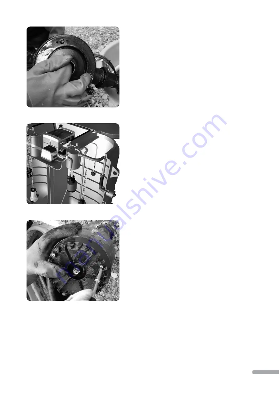
7.2.2 Cleaning of emptying
pump and sludge pump
The emptying pump and sludge
pump are inside the process tank
(section 1.7). Both pumps are
cleaned in the same way.
1.
Before service, remove the
control unit electrical socket
from the treatment plant ma-
chine room (picture 45).
2.
Open the hose clamp of the
emptying pump from the fl ush
tank and remove the pump
hose. Be careful not to drop
the clamp into the tank.
3.
Remove the mounting screws
of the fl ush tank.
4.
Lift the emptying pump up by
the fl ush tank handle (picture
49). The pump may be rinsed
to simplify service. It is also
recommended to clean the
fl ush tank when servicing the
pump.
5.
Use the attachment chain to
lift the sludge pump out of
the tank. The pump may be
rinsed to simplify service.
6.
Open the three screws at the
bottom of the pump
(picture 50).
7.
Remove the pump bottom
plate (pictures 51 and 52).
Remove any clogging.
8.
Aft er cleaning, ensure the free
rotation of the blade wheel
(picture 53).
Picture 48
Picture 49
Picture 50
9.
Reassemble the pump aft er
cleaning. Carefully reattach
the bottom plate screws! Clear
any accumulated dirt from
the pump attachment chain.
Lower the pump back into
the process tank by using the
chain.
10.
Aft er the service procedu-
res, remove the compressor
plug X3 and reconnect the
treatment plant control unit
electrical plug.
11.
Test pump operation by mo-
ving the plug of the cleaned
pump into socket X6. When
placing emptying pump plug
X1 in socket X6, the pump will
immediately start pumping
water from the process tank
to the discharge location.
If the surface is low in the
process tank, pump operation
may be verifi ed by listening
for pump operating noise.
The sludge pump is tested by
moving plug X4 into socket
X6. Sludge pumping should
begin immediately.
12.
Remember to move the
sockets back into their places!
13.
If the service procedures did
not help, order service.
NOTE! Avoid unnecessarily
pumping of untreated water
into the discharge location or
absorption fi eld!
27


