Page 3-27
Maintenance
3.19 - Torque Specifications
TL50 Service & Parts
3.19 T
ORQUE
S
PECIFICATIONS
H
YDRAULIC
C
OMPONENTS
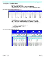
NOTE:
Always lubricate threads with clean hydraulic oil prior to installation
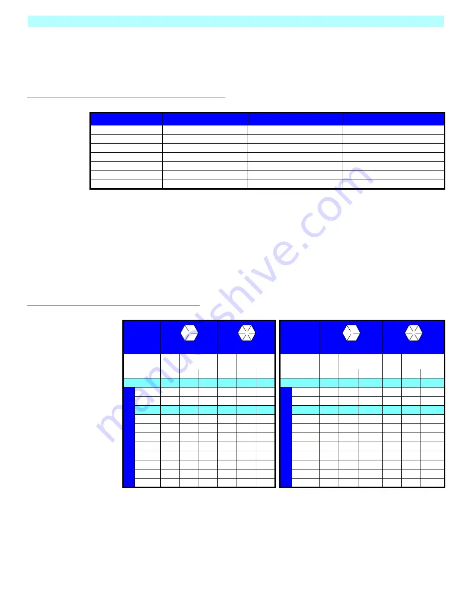
Use the following values to torque hydraulic components used on UpRight Work Platforms.
Table 3-1: Torque Specifications for Hydraulic Components
F
ASTENERS
This standard applies to the preloading of fasteners measured by installation torque.
NOTE:
For other preloading methods or fasteners, consult UpRight Engineering Department.
This general standard applies to all SAE and Metric fasteners, unless otherwise specified.
T
HREAD
C
ONDITION
• For lubed or zinc plated fasteners, use K = .15
• For dry unplated fasteners, use K = .20
T
ORQUE
T
ABLES
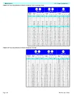
Table 3-2: Torque Specifications for SAE Fasteners
Type: SAE Part Series
Cartridge Poppet
Fittings
Hoses
Ft/Lbs
Nm
Ft/Lbs
Nm
Ft/Lbs
Nm
#4
N/A
N/A
N/A
N/A
135-145
15-16
#6
N/A
N/A
10-20
14-27
215-245
24-28
#8
25-30
34-41
25-30
34-41
430-470
49-53
#10
35-40
47-54
35-40
47-54
680-750
77-85
#12
85-90
115-122
85-90
115-122
950-1050
107-119
#16
130-140
176-190
130-140
176-190
1300-1368
147-155
SAE J429 Grade 5
SAE J429 Grade 8
SAE J429 Grade 5
SAE J429 Grade 8
Nominal
Thread Size
Clamp
Load
Tightening
Torque
Clamp
Load
Tightening
Torque
Nominal
Thread Size
Clamp
Load
Tightening
Torque
Clamp
Load
Tightening
Torque
K=.15 K=.20
K=.15 K=.20
K=.15
K=.20
K=.15
K=.20
lbs.
in-lbs. in-lbs.
lbs.
in-lbs. in-lbs.
lbs.
in-lbs.
in-lbs.
lbs.
in-lbs.
in-lbs.
U
n
if
ie
d Co
ar
se
Th
re
ad
Se
ri
e
s
1/4 -20
2,000
75
100
2850
107
143
Un
ifie
d
Fin
e
Th
re
ad
Se
rie
s
1/4 -28
2,300
85
115
3250
120
163
5/16 - 18 3,350
157
210
4700
220
305
5/16-24
3,700
173
230
5200
245
325
lbs.
ft-lbs. ft-lbs.
lbs.
ft-lbs. ft-lbs.
lbs.
ft-lbs.
ft-lbs.
lbs.
ft-lbs.
ft-lbs.
3/8-16
4,950
23
31
6950
32.5
44
3/8-24
5,600
26
35
7900
37
50
7/16-14
6,800
37
50
9600
53
70
7/16-20
7,550
42
55
10700
59
78
1/2-13
9,050
57
75
12800
80
107
1/2-20
10,200
64
85
14400
90
120
9/16-12 11,600
82
109
16400
115
154
9/16-18
13,000
92
122
18300
129
172
5/8-11
14,500
113
151
20300
159
211
5/8-18
16,300
128
170
23000
180
240
3/4-10
21,300
200
266
30100
282
376
3/4-16
23,800
223
298
33600
315
420
7/8-9
29,435
321
430
41550
454
606
7/8-14
32,480
355
473
45855
500
668
1-8
38,600
483
640
54540
680
900
1-12
42,270
528
704
59670
745
995
Summary of Contents for 503502-000
Page 1: ...ERVICE PARTS MANUAL POWERED ACCESS WORK PLATFORM TL50...
Page 21: ...Page 16 TL50 Service Parts Specifications Notes...
Page 51: ...Page 3 30 Maintenance 3 19 Torque Specifications TL50 Service Parts NOTES...
Page 59: ...Page 5 2 Schematics 5 1 Introduction TL50 Service Parts...
Page 60: ...Page 5 3 Schematics 5 1 Introduction TL50 Service Parts...
Page 61: ...Page 5 4 Schematics 5 1 Introduction TL50 Service Parts...
Page 62: ...Page 5 5 Schematics 5 1 Introduction TL50 Service Parts...
Page 63: ...Page 5 6 Schematics 5 1 Introduction TL50 Service Parts Notes...
Page 66: ...Page 6 3 Illustrated Parts Breakdown General Assembly TL50 Service Parts 1 1 2 3 4 5 6 7...
Page 70: ...Page 6 7 Illustrated Parts Breakdown Booms Posts Assembly TL50 Service Parts 44 45...
Page 72: ...Page 6 9 Illustrated Parts Breakdown Platform Assembly Standard TL50 Service Parts...
Page 74: ...Page 6 11 Illustrated Parts Breakdown Platform Assembly Rotator TL50 Service Parts...
Page 88: ...Page 6 25 Illustrated Parts Breakdown Hydraulic Tank Assembly TL50 Service Parts...
Page 90: ...Page 6 27 Illustrated Parts Breakdown Electrical Assembly TL50 Service Parts...
Page 92: ...Page 6 29 Illustrated Parts Breakdown Hydraulic Assembly TL50 Service Parts...
Page 94: ...Page 6 31 Illustrated Parts Breakdown Decal Assembly TL50 Service Parts...
Page 95: ...Page 6 32 Illustrated Parts Breakdown Decal Assembly TL50 Service Parts...
Page 96: ...Technician s Print TL50 W ork Platform Electrical Schematic...
Page 97: ...Technician s Print TL50 W ork Platform Harness Schematic...
Page 98: ......

