Introduction & Specifications
Section
1-2
AB38 Work Platform
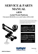
AB38 PURPOSE & LIMITATIONS
The purpose of the AB38 work platform is to provide a
quickly deployable variable height work platform. It is
capable of lifting two people with work tools up to an
upper limit of 215 kg (475 lbs) in total. The unit will
provide the ability to reach over obstacles but must
be used on firm level ground.
The platform must
only
be used on firm level or
slightly uneven ground capable of supporting the
maximum load generated under the four wheels.
Do
not
use on soft or severely sloping ground.
NOTE:
It should be recognised that if the tilt
switch senses a degree of slope greater than
3
°
the elevating circuits will lockout and
sound a warning alarm. The Emergency
Override should then be used, to lower the
Elevating Assembly.
DRIVE & STEER SYSTEMS
The AB38 Work Platform is restricted to low speed
drive when the Platform is raised above the Boom
Rest Limit Switch. The Traction controller controls the
application of drive from the Joystick by means of two
Traction Motors, which are assembled to the drive
wheels via a Drive Reduction Gearbox.
Steering of the AB38 Work Platform is controlled by
the ECU, which controls the signals activating a
double acting cylinder. An Operator can Steer left or
right by depressing the Rocker Switches on top of the
Joystick, while activating the Interlock Switch.
POWER SYSTEM
The power system incorporates eight 6V batteries
driving the drive traction motors, or the 4kW (5.4HP)
electric motor which in turn drives the hydraulic
pump. The application of this hydraulic pressure is
performed by the Control System.
CONTROL SYSTEM
The machine is provided with fully proportional
controls by means of the interaction between an
ECU, electronic motor controller and a proportional
joystick. The ECU and motor controller regulate the
drive motor/pump speed and hence the flow of oil
reaching the cylinders, the Worm Drive Unit or the
Drive Reduction Gearbox. It regulates the direction of
flow of the hydraulic oil via the solenoid valves located
on the manifold block, and it also monitors the opera-
tion of all switches on the machine via the machine
harness system.
The motor control units are located, in the left hand
chassis module. The manifold block is located on the
hydraulic tank. This is accessible by removing the
main cover.
CHASSIS
The chassis is a structural frame designed to support
all the components of the AB38 Work Platform.
1.1
DANGER
Summary of Contents for AB38
Page 2: ...ii AB38 Work Platform NOTES...
Page 4: ...ii AB38 Work Platform NOTES...
Page 6: ...iv AB38 Work Platform NOTES Foreword...
Page 10: ...Contents Section IV AB38 Work Platform i NOTES...
Page 14: ...Introduction Specifications Section 1 4 AB38 Work Platform NOTES 1 3...
Page 17: ...Machine Preparation Section 2 3 AB38 Work Platform NOTES 2 7...
Page 18: ...Machine Preparation Section 2 4 AB38 Work Platform 2 7 NOTES...
Page 29: ...Operation Section 3 11 AB38 Work Platform NOTES 3 5...
Page 30: ...Operation Section 3 12 AB38 Work Platform NOTES 3 5...
Page 59: ...Maintenance Section 4 29 AB38 Work Platform NOTES 4 21...
Page 60: ...Maintenance Section 4 30 AB38 Work Platform NOTES 4 21...
Page 66: ...Troubleshooting Section 5 6 AB38 Work Platform 5 7 NOTES...
Page 68: ...Schematics Section 6 2 AB38 Work Platform NOTES 6 0...
Page 72: ...Schematics Section 6 6 AB38 Work Platform 6 1 NOTES...
Page 73: ...Electrical Schematic Schematics 6 7 AB38 Work Platform Section 6 1...
Page 74: ...Electrical Schematic Schematics 6 8 AB38 Work Platform Section 6 1 TOP VIEW...
Page 76: ...Schematics Section 6 10 AB38 Work Platform NOTES 6 2...
Page 78: ...Section 6 2 6 12 AB38 Work Platform Schematics NOTES...
Page 81: ...Illustrated Parts Breakdown Section 7 3 AB38 Work Platform 7 2...
Page 83: ...Illustrated Parts Breakdown Section 7 5 AB38 Work Platform 7 2...
Page 85: ...Illustrated Parts Breakdown Section 7 7 AB38 Work Platform 7 2...
Page 87: ...Illustrated Parts Breakdown Section 7 9 AB38 Work Platform 7 2...
Page 89: ...Illustrated Parts Breakdown Section 7 11 AB38 Work Platform 7 2 22...
Page 91: ...Illustrated Parts Breakdown Section 7 13 AB38 Work Platform 7 2...
Page 93: ...Illustrated Parts Breakdown Section 7 15 AB38 Work Platform 7 2...
Page 95: ...Illustrated Parts Breakdown Section 7 17 AB38 Work Platform 7 2...
Page 97: ...Illustrated Parts Breakdown Section 7 19 AB38 Work Platform 7 2...
Page 99: ...Illustrated Parts Breakdown Section 7 21 AB38 Work Platform 7 2...
Page 101: ...Illustrated Parts Breakdown Section 7 23 AB38 Work Platform 7 2...
Page 103: ...Illustrated Parts Breakdown Section 7 25 AB38 Work Platform 7 2...
Page 105: ...Illustrated Parts Breakdown Section 7 27 AB38 Work Platform 7 2...
Page 107: ...Illustrated Parts Breakdown Section 7 29 AB38 Work Platform 7 2...
Page 109: ...Illustrated Parts Breakdown Section 7 31 AB38 Work Platform 7 2...
Page 111: ...Illustrated Parts Breakdown Section 7 33 AB38 Work Platform 7 2...
Page 113: ...Illustrated Parts Breakdown Section 7 35 AB38 Work Platform 7 2...
Page 115: ...Illustrated Parts Breakdown Section 7 37 AB38 Work Platform 7 2...
Page 117: ...Illustrated Parts Breakdown Section 7 39 AB38 Work Platform 7 2...
Page 119: ...Illustrated Parts Breakdown Section 7 41 AB38 Work Platform 7 2 8 9...
Page 121: ...Illustrated Parts Breakdown Section 7 43 AB38 Work Platform 7 2...
Page 123: ...Illustrated Parts Breakdown Section 7 45 AB38 Work Platform 7 2...
Page 125: ...Illustrated Parts Breakdown Section 7 47 AB38 Work Platform 7 2...
Page 127: ...Illustrated Parts Breakdown Section 7 49 AB38 Work Platform 7 2...
Page 131: ...Illustrated Parts Breakdown Section 7 53 AB38 Work Platform 7 2 NOTES...
Page 133: ...Technician s Print AB38 Work Platform Electrical Schematic...


