Operation
Section
3-8
AB38 Work Platform
CAUTION
5.
To “
STEER
” the AB38 activate the Interlock
Switch while pushing the Steering Switch
LEFT
or
RIGHT
to turn the wheels. Observe the tyres
while manoeuvring to ensure proper direction.
NOTE:
Steering is not self-centring. The wheels must be
returned to the straight ahead position by operating
the Steering Switch.
TRAVEL WITH WORK PLATFORM
ELEVATED
Travel with platform elevated
ONLY
on firm
and level surfaces. Platform motion is
exaggerated while travelling on uneven
surfaces.
NOTE:
The Work Platform will travel at reduced speed when
in the elevated position.
1.
Check that the route is clear of persons,
obstructions, pot holes or ledges and is capable
of supporting the wheel loads. Also, check that
the clearances above, below and to the side of
the Work Platform are sufficient.
2.
Depress the Drive function button.
3.
Grasp the Joystick so that the Interlock Switch
is depressed (releasing this Interlock Switch will
cut power to the Joystick). Slowly push or pull
the Joystick to
FORWARD
or
REVERSE
to
travel in the desired direction. The farther you
push or pull the Joystick from the center the
faster the machine will travel.
If the machine comes to a halt and the Tilt
Alarm sounds, immediately lower the
Platform and move the machine to a level
location before re-elevating the Platform.
PLATFORM LEVELLING
NOTE:
The Levelling function will only work when the Boom
Rest Limit Switch has been activated i.e. when the
Booms are stowed.
The platform can be levelled from the Upper controls
using the levelling function, depress and hold the
levelling button on the upper control box (see fig3-1)
while moving the joystick forward or back to level the
platform. The switch should be operated in short
bursts to level the platform
slowly.
EMERGENCY SITUATIONS &
EMERGENCY OVERRIDE
In any emergency situation, the first action to be taken
should be to hit the red “Emergency Stop”
button for instant cutout of all functions. It will then be
required to twist the button clockwise, this releases
the cutout and the machine can be operated again.
If the audible Tilt warning alarm sounds, normal
control functions will cease to operate. This will be
due to the following problem ;
l
the machine is out of level i.e. Tilt Sensor has
been activated.
In this situation the only machine functions that will
operate are descent functions, descend to the ground
in a controlled manner and cycle the power (push and
release the emergency stop) to restore all functions,
move the machine to a level surface and continue
with normal operation.
Note that during emergency operation, controls
will operate at a fixed, slow speed and will not
allow the raising or extending of the Booms.
The Booms can be lowered or retracted.
Emergency Lowering
When operating this function, extreme care
must be taken to ensure that the person
carrying out the task does not become
trapped by the structure.
DO NOT
climb
down the Elevating Assembly to operate
these valves.
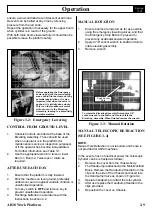
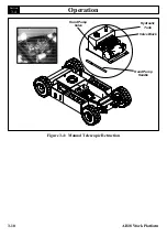
Should the machine become inoperable when
elevated, request a person on the ground to lower the
platform using the emergency lowering valves.
These are red knobs (push type) mounted at the
base of the 2 Main Hydraulic Lift Cylinders (See
Figure 3-2).
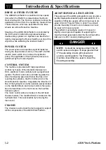
Operate the lower boom first by pushing slowly.
The boom will descend slowly. The speed of descent
is controlled by retaining pressure on the valve -
3.4
CAUTION
WARNING
Summary of Contents for AB38
Page 2: ...ii AB38 Work Platform NOTES...
Page 4: ...ii AB38 Work Platform NOTES...
Page 6: ...iv AB38 Work Platform NOTES Foreword...
Page 10: ...Contents Section IV AB38 Work Platform i NOTES...
Page 14: ...Introduction Specifications Section 1 4 AB38 Work Platform NOTES 1 3...
Page 17: ...Machine Preparation Section 2 3 AB38 Work Platform NOTES 2 7...
Page 18: ...Machine Preparation Section 2 4 AB38 Work Platform 2 7 NOTES...
Page 29: ...Operation Section 3 11 AB38 Work Platform NOTES 3 5...
Page 30: ...Operation Section 3 12 AB38 Work Platform NOTES 3 5...
Page 59: ...Maintenance Section 4 29 AB38 Work Platform NOTES 4 21...
Page 60: ...Maintenance Section 4 30 AB38 Work Platform NOTES 4 21...
Page 66: ...Troubleshooting Section 5 6 AB38 Work Platform 5 7 NOTES...
Page 68: ...Schematics Section 6 2 AB38 Work Platform NOTES 6 0...
Page 72: ...Schematics Section 6 6 AB38 Work Platform 6 1 NOTES...
Page 73: ...Electrical Schematic Schematics 6 7 AB38 Work Platform Section 6 1...
Page 74: ...Electrical Schematic Schematics 6 8 AB38 Work Platform Section 6 1 TOP VIEW...
Page 76: ...Schematics Section 6 10 AB38 Work Platform NOTES 6 2...
Page 78: ...Section 6 2 6 12 AB38 Work Platform Schematics NOTES...
Page 81: ...Illustrated Parts Breakdown Section 7 3 AB38 Work Platform 7 2...
Page 83: ...Illustrated Parts Breakdown Section 7 5 AB38 Work Platform 7 2...
Page 85: ...Illustrated Parts Breakdown Section 7 7 AB38 Work Platform 7 2...
Page 87: ...Illustrated Parts Breakdown Section 7 9 AB38 Work Platform 7 2...
Page 89: ...Illustrated Parts Breakdown Section 7 11 AB38 Work Platform 7 2 22...
Page 91: ...Illustrated Parts Breakdown Section 7 13 AB38 Work Platform 7 2...
Page 93: ...Illustrated Parts Breakdown Section 7 15 AB38 Work Platform 7 2...
Page 95: ...Illustrated Parts Breakdown Section 7 17 AB38 Work Platform 7 2...
Page 97: ...Illustrated Parts Breakdown Section 7 19 AB38 Work Platform 7 2...
Page 99: ...Illustrated Parts Breakdown Section 7 21 AB38 Work Platform 7 2...
Page 101: ...Illustrated Parts Breakdown Section 7 23 AB38 Work Platform 7 2...
Page 103: ...Illustrated Parts Breakdown Section 7 25 AB38 Work Platform 7 2...
Page 105: ...Illustrated Parts Breakdown Section 7 27 AB38 Work Platform 7 2...
Page 107: ...Illustrated Parts Breakdown Section 7 29 AB38 Work Platform 7 2...
Page 109: ...Illustrated Parts Breakdown Section 7 31 AB38 Work Platform 7 2...
Page 111: ...Illustrated Parts Breakdown Section 7 33 AB38 Work Platform 7 2...
Page 113: ...Illustrated Parts Breakdown Section 7 35 AB38 Work Platform 7 2...
Page 115: ...Illustrated Parts Breakdown Section 7 37 AB38 Work Platform 7 2...
Page 117: ...Illustrated Parts Breakdown Section 7 39 AB38 Work Platform 7 2...
Page 119: ...Illustrated Parts Breakdown Section 7 41 AB38 Work Platform 7 2 8 9...
Page 121: ...Illustrated Parts Breakdown Section 7 43 AB38 Work Platform 7 2...
Page 123: ...Illustrated Parts Breakdown Section 7 45 AB38 Work Platform 7 2...
Page 125: ...Illustrated Parts Breakdown Section 7 47 AB38 Work Platform 7 2...
Page 127: ...Illustrated Parts Breakdown Section 7 49 AB38 Work Platform 7 2...
Page 131: ...Illustrated Parts Breakdown Section 7 53 AB38 Work Platform 7 2 NOTES...
Page 133: ...Technician s Print AB38 Work Platform Electrical Schematic...

