Troubleshooting
Section
5-2
AB38 Work Platform
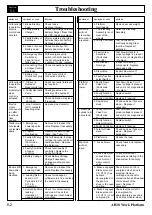
PROBLEM
PROBABLE CAUSE
REMEDY
PROBLEM
PROBABLE CAUSE
REMEDY
All functions 1. Blown Electric
Check fuses,
inoperable.
Fuse.
Replace if blown.
Electric
2. Faulty Battery
Check the voltage output of
motor does
Charger.
battery charger. If less than
not start.
24 VDC, repair or replace.
3. Faulty Battery or
After completely charging
Batteries.
batteries test each battery.
Replace as required.
4. Loose or broken
Check continuity of all
Battery Lead.
battery and motor leads.
Replace if necessary.
5. Emergency Stop
With emergency stop
Switch(es)
switch in the ON position,
upper & lower
check continuity across
failed open.
contacts. If none, replace.
6. Connecting Plug
Check connection and retry.
at Upper Control
Box loose.
7. Battery Line
Check for security of
Disconnect plug
connection and retry.
loose.
All functions 1. Oil level in
Check hydraulic fluid level,
inoperable.
Hydraulic
as required.
Electric
Reservoir is low.
motor starts 2. Faulty Hydraulic
Check pressure and
when
Pump.
delivery of the hydraulic
control is
pump. Replace if required.
actuated.
3. Faulty
Check operation. Replace
Controller.
if required.
Electric
1. Line Contactor
Replace Line Contactor.
motor
(LC1) contacts
continues to
fused together.
run after
functions
have
ceased.
Platform will 1. Emergency
Remove and inspect the
not elevate
Lowering valve
valve. Replace if necessary.
or elevates
leaking.
slowly.
2. Platform
Observe maximum load
Overloaded.
rating. (See Table 1-1).
3. Faulty Lift Valve
Test Lift Solenoid, if proper
Solenoid.
voltage is present and coil
(Fault code :
unmagnetized - Replace
51 or 53)
the Solenoid.
4. Faulty Controller
Check functionality of
at upper
controller. Replace the
controls.
Controller if faulty.
5. Battery Voltage.
Check Battery Voltage.
Charge if necessary.
Voltage must be greater
than 14V.
Booms drift
1. Emergency
Remove and inspect the
down after
Lowering Valve
valve. Replace if necessary.
being
is leaking.
elevated.
2. Leaking piston
Check for leakage at
seals in Lift
cylinder return line, replace
Cylinders (CYL1, the seal kit if necessary.
CYL2 &
Telescope).
3. Overcentre Valve
Check for contamination
leaking
and clean. Check that
internally or
O-Rings are intact. Adjust
needs adjusting. or replace.
4. Platform
Remove excess weight.
Overloaded.
Machine
1. The Elevating
Raise the Elevating
will not
Assembly is not
Assembly.
slew when
clear of the
Booms are
wheels.
elevated.
2.Faulty Controller
Test Controller for
continuity during Slew
function. Replace if
defective.
3. Faulty Slew
Test Slew Solenoid, if
Solenoid.
proper voltage is present
(Fault code :
and coil is not magnetized
57 or 58)
- Replace
4. Mechanical
Inspect all slewing
Damage.
components. Replace
damaged parts.
5. Slew Valve
Inspect slew valve. If
stuck.
spool is sticking - Replace.
6. Faulty function
Replace switch.
select Switch.
Platform
1.Faulty Down
Test Down Valve Coil. If
will not
Valve Coil
proper voltage is present
lower.
(Fault code :
and coil is not magnetised
52 or 54)
- Replace
2.Faulty function
Replace switch.
Selector Switch.
3.Faulty Controller
Replace if required.
4.Down Valve
Check and see if spool is
stuck.
stuck. - Replace if
necessary.
Telescopic
1.Faulty Tele-Out
Test Tele-out Valve Coil. If
cylinder will
Valve Coil.
proper voltage is present
not extend.
(Fault code :
and coil is not magnetised
55 or 56)
- Replace.
2.Faulty function
Replace switch.
Selector Switch.
3.Faulty Controller.
Replace if required.
4.Tele-Out Valve
Check and see if spool is
stuck.
stuck. - Replace if
necessary.
5.Platform is
Reduce the load
overloaded.
Machine
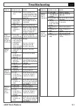
1. Fuses blown.
Check fuses and replace if
will not
necessary
drive.
2. Loose electrical
Check all electrical
connection on
connections relating to the
drive motor or
drive system for security.
motor control
units.
3. Brakes engaged Check that coil of V2 is
Brake solenoid
energised when drive is
V2 ( CT12 ) has
selected. Remove
become
cartridge and check for
de-energised or
contamination and freedom
the spool is
of movement of the
stuck in the open spool. Replace if
position.
necessary.
4. Brakes engaged Check that the coil of V1
Brake solenoid
is energised for
V1 ( CT11 ) is not approximately 4 seconds,
energising to
by a delay module, when
5.1
Summary of Contents for AB38
Page 2: ...ii AB38 Work Platform NOTES...
Page 4: ...ii AB38 Work Platform NOTES...
Page 6: ...iv AB38 Work Platform NOTES Foreword...
Page 10: ...Contents Section IV AB38 Work Platform i NOTES...
Page 14: ...Introduction Specifications Section 1 4 AB38 Work Platform NOTES 1 3...
Page 17: ...Machine Preparation Section 2 3 AB38 Work Platform NOTES 2 7...
Page 18: ...Machine Preparation Section 2 4 AB38 Work Platform 2 7 NOTES...
Page 29: ...Operation Section 3 11 AB38 Work Platform NOTES 3 5...
Page 30: ...Operation Section 3 12 AB38 Work Platform NOTES 3 5...
Page 59: ...Maintenance Section 4 29 AB38 Work Platform NOTES 4 21...
Page 60: ...Maintenance Section 4 30 AB38 Work Platform NOTES 4 21...
Page 66: ...Troubleshooting Section 5 6 AB38 Work Platform 5 7 NOTES...
Page 68: ...Schematics Section 6 2 AB38 Work Platform NOTES 6 0...
Page 72: ...Schematics Section 6 6 AB38 Work Platform 6 1 NOTES...
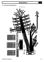
Page 73: ...Electrical Schematic Schematics 6 7 AB38 Work Platform Section 6 1...
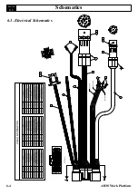
Page 74: ...Electrical Schematic Schematics 6 8 AB38 Work Platform Section 6 1 TOP VIEW...
Page 76: ...Schematics Section 6 10 AB38 Work Platform NOTES 6 2...
Page 78: ...Section 6 2 6 12 AB38 Work Platform Schematics NOTES...
Page 81: ...Illustrated Parts Breakdown Section 7 3 AB38 Work Platform 7 2...
Page 83: ...Illustrated Parts Breakdown Section 7 5 AB38 Work Platform 7 2...
Page 85: ...Illustrated Parts Breakdown Section 7 7 AB38 Work Platform 7 2...
Page 87: ...Illustrated Parts Breakdown Section 7 9 AB38 Work Platform 7 2...
Page 89: ...Illustrated Parts Breakdown Section 7 11 AB38 Work Platform 7 2 22...
Page 91: ...Illustrated Parts Breakdown Section 7 13 AB38 Work Platform 7 2...
Page 93: ...Illustrated Parts Breakdown Section 7 15 AB38 Work Platform 7 2...
Page 95: ...Illustrated Parts Breakdown Section 7 17 AB38 Work Platform 7 2...
Page 97: ...Illustrated Parts Breakdown Section 7 19 AB38 Work Platform 7 2...
Page 99: ...Illustrated Parts Breakdown Section 7 21 AB38 Work Platform 7 2...
Page 101: ...Illustrated Parts Breakdown Section 7 23 AB38 Work Platform 7 2...
Page 103: ...Illustrated Parts Breakdown Section 7 25 AB38 Work Platform 7 2...
Page 105: ...Illustrated Parts Breakdown Section 7 27 AB38 Work Platform 7 2...
Page 107: ...Illustrated Parts Breakdown Section 7 29 AB38 Work Platform 7 2...
Page 109: ...Illustrated Parts Breakdown Section 7 31 AB38 Work Platform 7 2...
Page 111: ...Illustrated Parts Breakdown Section 7 33 AB38 Work Platform 7 2...
Page 113: ...Illustrated Parts Breakdown Section 7 35 AB38 Work Platform 7 2...
Page 115: ...Illustrated Parts Breakdown Section 7 37 AB38 Work Platform 7 2...
Page 117: ...Illustrated Parts Breakdown Section 7 39 AB38 Work Platform 7 2...
Page 119: ...Illustrated Parts Breakdown Section 7 41 AB38 Work Platform 7 2 8 9...
Page 121: ...Illustrated Parts Breakdown Section 7 43 AB38 Work Platform 7 2...
Page 123: ...Illustrated Parts Breakdown Section 7 45 AB38 Work Platform 7 2...
Page 125: ...Illustrated Parts Breakdown Section 7 47 AB38 Work Platform 7 2...
Page 127: ...Illustrated Parts Breakdown Section 7 49 AB38 Work Platform 7 2...
Page 131: ...Illustrated Parts Breakdown Section 7 53 AB38 Work Platform 7 2 NOTES...
Page 133: ...Technician s Print AB38 Work Platform Electrical Schematic...

