3-6
SL26/30SL Work Platform
M
AINTENANCE
Section
3.7
3.7 S
ETTING
H
YDRAULIC
P
RESSURES
Referring to Figure 3-13 along with the other Figures
will aid in the following procedures.
Note: Check the hydraulic pressures whenever
the pump, manifold, or relief valve(s) have been
serviced or replaced.
Main Relief Valve (Figure 3-4)
1. Operate the hydraulic system for five minutes.
2. Remove the gauge port plug (Figure 3-5) and
install a quick disconnect gauge assembly.
3. Remove the plug in the end of the main relief
valve to expose the adjusting screw.
4. Remove the hex nut holding the lift coil onto the
lift valves and remove coil.
5. With the engine running, use the chassis lift
switch to elevate the platform, hold until the sys-
tem bypasses (approximately 2 seconds).
6. While holding the chassis lift switch in the
UP
position, set the pressure to 172 bar (2500 psi)
maximum by slowly turning the adjusting screw,
clockwise increases pressure.
7. Reinstall the coil on the lift valve.
8. Remove the pressure gauge and reinstall all
plugs.
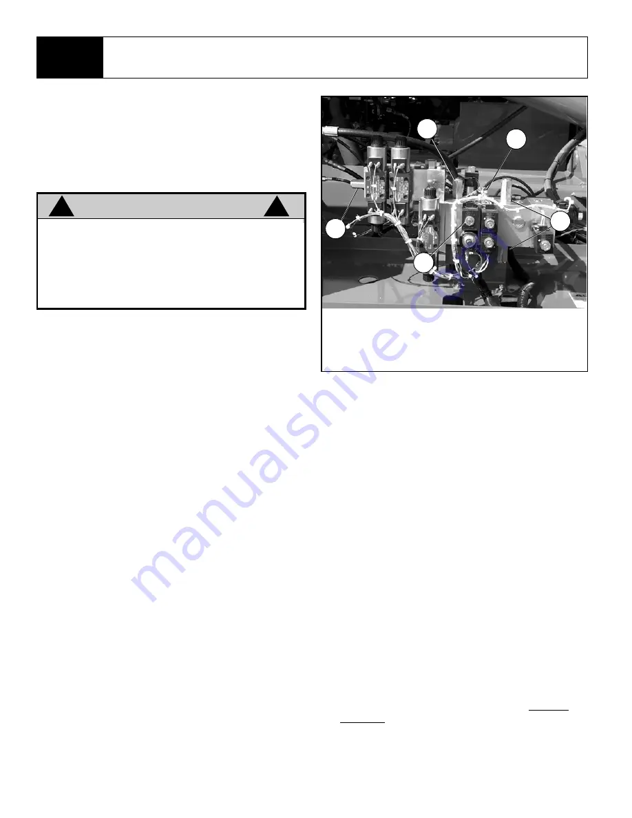
Figure 3-4: Hydraulic Manifold Assembly, Front View
Counterbalance Valves (Figure 3-4)
1. Operate the hydraulic system for five minutes to
warm the oil.
2. Remove the quick disconnect plug (Figure 3-5)
and install a 0-41 bar (0-600 psi) pressure gauge
assembly.
3. Exchange the top Counterbalance Valve with the
Main Relief Valve.
4. Remove the plug from the end of the Counterbal-
ance Valve to expose the adjusting screw.
5. Remove the hex nut holding the lift coil onto the
lift valve and remove the coils.
6. With the engine running, use the chassis lift
switch to elevate the platform, hold until the sys-
tem bypasses (approximately 2 seconds).
7. While holding the chassis lift switch in the
UP
position, set the pressure to 34.5 bar (500 psi)
maximum by slowly turning the adjusting screw,
clockwise increases pressure.
8. Exchange the top Counterbalance Valve with the
bottom Counterbalance Valve and repeat the pro-
cedure.
9. Be sure to reinstall the valves to their original
locations and replace all plugs when finished set-
ting pressures.
W A R N I N G
!
!
The hydraulic oil may be of sufficient tempera-
ture to cause burns. Wear safety gloves and
safety glasses when handling hot oil.
The oil in the hydraulic system is under very
high pressure which can easily cause severe
cuts. Obtain medical assistance
immediately
if
cut by hydraulic oil.
1
2
3
4
1. Main Relief Valve
2. Counterbalance
Valves
3. Lift Coil
4. Steering Relief
Valve
5. Quick Disconnect
5
Summary of Contents for SL26SL
Page 1: ...European Specification ...
Page 4: ...ii SL26 30SL Work Platform FORWARD NOTES ...
Page 12: ...1 4 SL26 30SL Work Platform INTRODUCTION SPECIFICATIONS Section 1 3 NOTES ...
Page 24: ...2 12 SL26 30SL Work Platform MACHINE PREPARATION OPERATION Section 2 13 NOTES ...
Page 48: ...4 6 SL26 30SL Work Platform TROUBLESHOOTING Section 4 2 NOTES ...
Page 54: ...5 6 SL26 30SL Work Platform SCHEMATICS Section 5 2 NOTES ...
Page 59: ...SL26 30SL Work Platform 6 5 ILLUSTRATED PARTS BREAKDOWN 6 1 NOTES ...
Page 63: ...SL26 30SL Work Platform 6 9 ILLUSTRATED PARTS BREAKDOWN 6 1 NOTES ...
Page 65: ...SL26 30SL Work Platform 6 11 ILLUSTRATED PARTS BREAKDOWN 6 1 ...
Page 67: ...SL26 30SL Work Platform 6 13 ILLUSTRATED PARTS BREAKDOWN 6 1 ...
Page 69: ...SL26 30SL Work Platform 6 15 ILLUSTRATED PARTS BREAKDOWN 6 1 ...
Page 71: ...SL26 30SL Work Platform 6 17 ILLUSTRATED PARTS BREAKDOWN 6 1 ...
Page 83: ...SL26 30SL Work Platform 6 29 ILLUSTRATED PARTS BREAKDOWN 6 1 ...
Page 85: ...SL26 30SL Work Platform 6 31 ILLUSTRATED PARTS BREAKDOWN 6 1 ...
Page 95: ...SL26 30SL Work Platform 6 41 ILLUSTRATED PARTS BREAKDOWN 6 1 ...
Page 97: ...SL26 30SL Work Platform 6 43 ILLUSTRATED PARTS BREAKDOWN 6 1 ...
Page 99: ...SL26 30SL Work Platform 6 45 ILLUSTRATED PARTS BREAKDOWN 6 1 ...
Page 101: ...SL26 30SL Work Platform 6 47 ILLUSTRATED PARTS BREAKDOWN 6 1 ...
Page 103: ......


