SL26/30SL Work Platform
3-9
M
AINTENANCE
Section
3.8
4. Elevate the machine until the lower tension mem-
ber clears the limit switch lever. Set the LO
RANGE potentiometer so that the machine will
travel 6.1 m (20 ft.) in 27 to 28 at full controller
deflection.
Note: The machine should be running full speed
before crossing the starting line, and should
run perfectly straight through the course.
5. Repeat the speed trials for verification and read-
just as necessary.
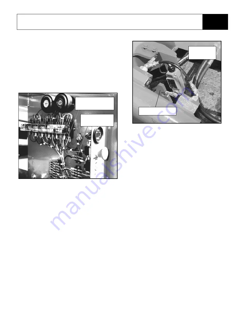
Figure 3-9: Platform Down Relay & Terminal Block
Axle Center Switch (Figure 3-10)
1. Check tires for proper pressure.
2. Place the work platform on a level surface with
the front and rear axles parallel (on the same
plane).
3. Adjust the switch so it is centered in the front axle
actuator linkage. When centered, the switch will
close the circuit.
4. Test the switch function by positioning the front
axle off-center and raising the platform 2.21-2.26
m (87-89 in.) above the ground. The work plat-
form should not drive. Retest with axle off-center
in the other position.
Figure 3-10: Axle Center Switch
Cushion Down Limit Switch
(Figure 3-11)
The cushion down limit switch is a mercury switch
that provides power to energize the cushion valve
during the last 30 cm (12 in.) of platform lowering.
1. Raise the platform 30 cm (12 in.) from its’ fully
lowered position.
2. Disconnect the wires at the mercury switch and
connect an ohmmeter or continuity tester.
3. Rotate the switch until it just closes. If necessary,
tighten the locknut that mounts the switch.
4. Raise and lower the platform to verify the adjust-
ment.
5. Disconnect ohmmeter and reconnect wires.
6. Lower platform.
Platform Down
Relay “A” Terminal
Small Terminal
Block
Axle Center
Switch
Actuator Linkage
Summary of Contents for SL26SL
Page 1: ...European Specification ...
Page 4: ...ii SL26 30SL Work Platform FORWARD NOTES ...
Page 12: ...1 4 SL26 30SL Work Platform INTRODUCTION SPECIFICATIONS Section 1 3 NOTES ...
Page 24: ...2 12 SL26 30SL Work Platform MACHINE PREPARATION OPERATION Section 2 13 NOTES ...
Page 48: ...4 6 SL26 30SL Work Platform TROUBLESHOOTING Section 4 2 NOTES ...
Page 54: ...5 6 SL26 30SL Work Platform SCHEMATICS Section 5 2 NOTES ...
Page 59: ...SL26 30SL Work Platform 6 5 ILLUSTRATED PARTS BREAKDOWN 6 1 NOTES ...
Page 63: ...SL26 30SL Work Platform 6 9 ILLUSTRATED PARTS BREAKDOWN 6 1 NOTES ...
Page 65: ...SL26 30SL Work Platform 6 11 ILLUSTRATED PARTS BREAKDOWN 6 1 ...
Page 67: ...SL26 30SL Work Platform 6 13 ILLUSTRATED PARTS BREAKDOWN 6 1 ...
Page 69: ...SL26 30SL Work Platform 6 15 ILLUSTRATED PARTS BREAKDOWN 6 1 ...
Page 71: ...SL26 30SL Work Platform 6 17 ILLUSTRATED PARTS BREAKDOWN 6 1 ...
Page 83: ...SL26 30SL Work Platform 6 29 ILLUSTRATED PARTS BREAKDOWN 6 1 ...
Page 85: ...SL26 30SL Work Platform 6 31 ILLUSTRATED PARTS BREAKDOWN 6 1 ...
Page 95: ...SL26 30SL Work Platform 6 41 ILLUSTRATED PARTS BREAKDOWN 6 1 ...
Page 97: ...SL26 30SL Work Platform 6 43 ILLUSTRATED PARTS BREAKDOWN 6 1 ...
Page 99: ...SL26 30SL Work Platform 6 45 ILLUSTRATED PARTS BREAKDOWN 6 1 ...
Page 101: ...SL26 30SL Work Platform 6 47 ILLUSTRATED PARTS BREAKDOWN 6 1 ...
Page 103: ......


