3-10
SL26/30SL Work Platform
M
AINTENANCE
Section
3.8
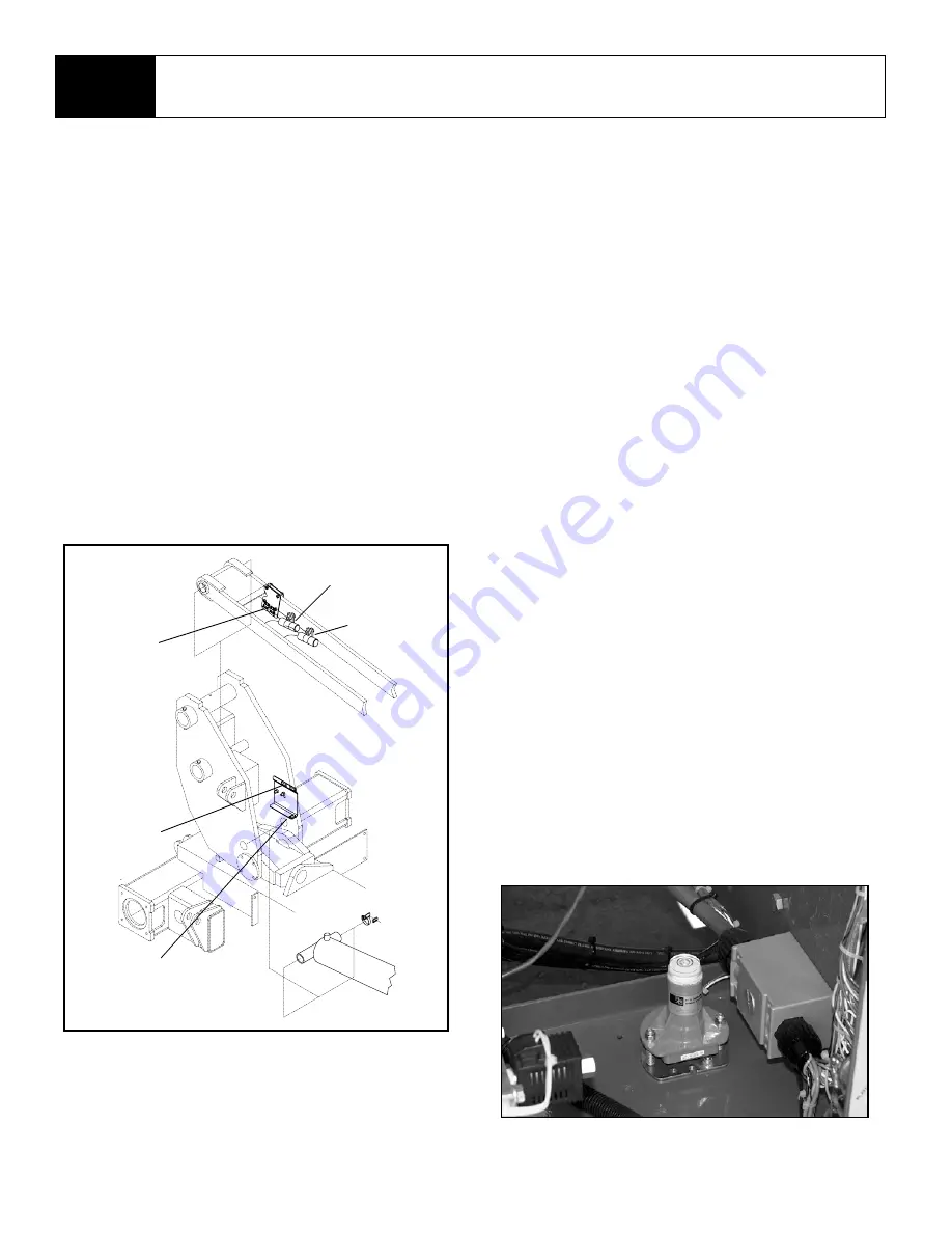
Lift Cutout Limit Switch (Figure 3-11)
The lift cutout limit switch is a mercury switch that
prevents the lift cylinder from bottoming out when the
platform is raised.
1. Raise the platform to its’ maximum height (mer-
cury switch may need to be rotated if switch is
cutting out lift function before cylinder bottoms
out).
2. Mark the cylinder rod 25.4 mm (1 in.) from base
of the rod. Lower platform slightly so the mark is
at cylinder head cap.
3. Disconnect the wires at the mercury switch and
connect an ohmmeter or continuity tester.
4. Rotate the switch until it just opens. If necessary,
tighten the locknut that mounts the switch.
5. Raise and lower the platform to verify the adjust-
ment.
6. Lower platform.
Figure 3-11: Limit Switch Locations
Down Limit Switch (Figure 3-11)
The down limit switches are dual proximity switches
which allow the machine to run at HI speed when the
platform is lowered.
1. Raise the platform 30 cm (12 in.) from its’ fully
lowered position.
2. Disconnect the wires at the proximity switches
and connect an ohmmeter or continuity tester.
3. Move the brackets holding the magnets so the
switch just closes. Tighten the locknuts that hold
the brackets.
4. Raise and lower the platform to verify the adjust-
ment.
5. Disconnect ohmmeter and reconnect wires.
6. Lower platform.
Tilt Sensor (Figure 3-12)
The tilt sensor has three wires; red-power (12v in),
black-ground, white-output (12v out). To verify the
sensor is working properly, there is one LED under
the sensor; red indicates the sensor is out of level
and the white wire is “hot” (12v out).
1. Level the platform with the platform controls using
the inclinometer (p/n: 010119-000) to ensure the
platform is level ±1/4°. side-to-side and front-to-
back.
2. Adjust the platform bubble level with the three lev-
eling screws until the bubble is centered in the cir-
cle on the bubble level.
3. Dismount the platform and remove the cover from
the back of the mast pivot weldment.
4. Adjust the three leveling locknuts on the tilt sen-
sor until the bubble is centered in the circle on the
attaches bubble level.
5. Replace the mast pivot weldment cover.
Figure 3-12: Tilt Sensor Adjustment
Cushion Down
Limit Switch
Lift Cutout
Limit Switch
Magnets
Down Limit
Switches
8 Meter Cutout
Limit Switch
Summary of Contents for SL26SL
Page 1: ...European Specification ...
Page 4: ...ii SL26 30SL Work Platform FORWARD NOTES ...
Page 12: ...1 4 SL26 30SL Work Platform INTRODUCTION SPECIFICATIONS Section 1 3 NOTES ...
Page 24: ...2 12 SL26 30SL Work Platform MACHINE PREPARATION OPERATION Section 2 13 NOTES ...
Page 48: ...4 6 SL26 30SL Work Platform TROUBLESHOOTING Section 4 2 NOTES ...
Page 54: ...5 6 SL26 30SL Work Platform SCHEMATICS Section 5 2 NOTES ...
Page 59: ...SL26 30SL Work Platform 6 5 ILLUSTRATED PARTS BREAKDOWN 6 1 NOTES ...
Page 63: ...SL26 30SL Work Platform 6 9 ILLUSTRATED PARTS BREAKDOWN 6 1 NOTES ...
Page 65: ...SL26 30SL Work Platform 6 11 ILLUSTRATED PARTS BREAKDOWN 6 1 ...
Page 67: ...SL26 30SL Work Platform 6 13 ILLUSTRATED PARTS BREAKDOWN 6 1 ...
Page 69: ...SL26 30SL Work Platform 6 15 ILLUSTRATED PARTS BREAKDOWN 6 1 ...
Page 71: ...SL26 30SL Work Platform 6 17 ILLUSTRATED PARTS BREAKDOWN 6 1 ...
Page 83: ...SL26 30SL Work Platform 6 29 ILLUSTRATED PARTS BREAKDOWN 6 1 ...
Page 85: ...SL26 30SL Work Platform 6 31 ILLUSTRATED PARTS BREAKDOWN 6 1 ...
Page 95: ...SL26 30SL Work Platform 6 41 ILLUSTRATED PARTS BREAKDOWN 6 1 ...
Page 97: ...SL26 30SL Work Platform 6 43 ILLUSTRATED PARTS BREAKDOWN 6 1 ...
Page 99: ...SL26 30SL Work Platform 6 45 ILLUSTRATED PARTS BREAKDOWN 6 1 ...
Page 101: ...SL26 30SL Work Platform 6 47 ILLUSTRATED PARTS BREAKDOWN 6 1 ...
Page 103: ......


