SL26/30SL Work Platform
5-3
S
CHEMATICS
Section
5.1
SEN1
Sensor, Level
Cuts power to Cutout Relay when
platform is out of level 2°
Inside mast pivot
weldment
SOL1
Solenoid, Steer
Right (Coil)
Shifts Steer Valve to right turn
position
Valve Manifold
SOL2
Solenoid, Steer Left
(Coil)
Shifts Steer Valve to left turn
position
Valve Manifold
SOL3
Solenoid, Forward
(Coil)
Opens Forward Valve to direct oil
through drive circuit for forward
Valve Manifold
SOL4
Solenoid, Reverse
Opens Reverse Valve to direct oil
through drive circuit for reverse
Valve Manifold
SOL5
Solenoid, Up (Coil)
Opens Lift Valve
Valve Manifold
SOL6
Solenoid, Down
(Coil)
Opens Down Valve
Valve Manifold
SOL7
Solenoid,
Proportional (Coil)
Controls Proportional Valve
Valve Manifold
SOL8
Solenoid, Cushion
(Coil)
Opens Cushion Down Valve to slow
descent during last 6 in. of travel
Valve Manifold
SOL9,10
Solenoids, Series/
Parallel (Coil)
Opens Series/Parallel Valve to
allow high speed drive
Valve Manifold
SOL11
Solenoid, Axle Float
(Coil)
Locks front axle when platform is
elevated
Side of Hydraulic
Tank
SOL12
Solenoid, Tilt
Forward (Coil)
Opens Tilt Fore Valve to direct oil to
tilt platform forward
Auxiliary Valve
Manifold
SOL13
Solenoid, Tilt Aft
(Coil)
Opens Tilt Aft Valve to direct oil to
tilt platform to the rear
Auxiliary Valve
Manifold
SOL14
Solenoid, Tilt Right
(Coil)
Opens Tilt Right Valve to direct oil
to tilt platform to the right
Auxiliary Valve
Manifold
SOL15
Solenoid, Tilt Left
(Coil)
Opens Tilt Left Valve to direct oil to
tilt platform to the Left
Auxiliary Valve
Manifold
SOL16
Solenoid, Steer
Bypass
Closes Steer Bypass Valve to direct
oil to steering or tilt circuits
Auxiliary Valve
Manifold
STR
Starter, Motor
Starts engine when Starter Relay is
energized
Power Module
DESIGNA
TION
NAME
FUNCTION
LOCATION
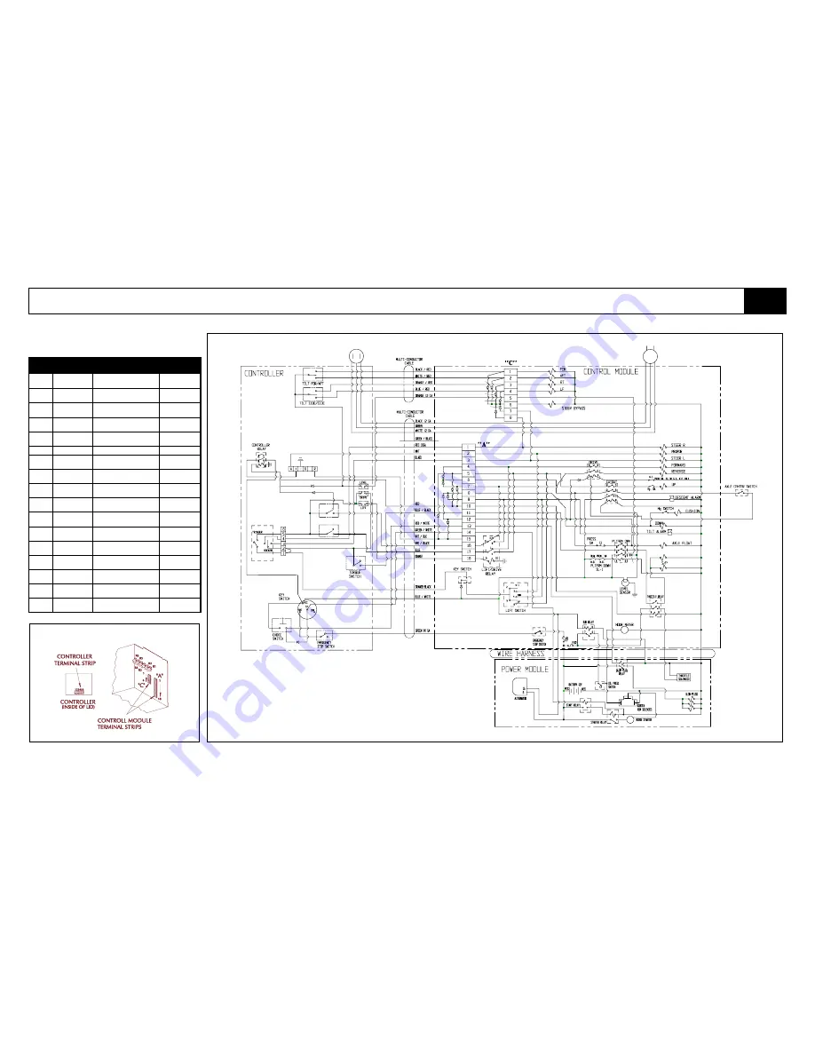
Figure 5-1: Terminal Strip & Relay Identification,
Diesel Model
Figure 5-2: Electrical Schematic - Diesel (064149-080)
S12
S13
R7
D11
D9
S1
S4,S5
S2
S3
S9
S8
S7
S6
S17
S11
R5
D1
D2
D3
D4
D5
D6
D7
D8
R6
BAT
F1
SEN1
R1
PS2
SOL9
SOL10
SOL11
ALM2
LS2
SOL8
SOL6
ALM1
SOL5
SOL1
SOL7
SOL2
SOL3
SOL4
LS3
R3
R2
D10
LS1
D16
D15
D17
D14
D13
SOL16
SOL15
SOL14
SOL13
SOL12
F2
S10
PS1
ALT
R8
R9
CO2
R10
CO1
HM
R4
S14
D19
S15
S16
D12
D20
STR
RES1
D18
Summary of Contents for SL26SL
Page 1: ...European Specification ...
Page 4: ...ii SL26 30SL Work Platform FORWARD NOTES ...
Page 12: ...1 4 SL26 30SL Work Platform INTRODUCTION SPECIFICATIONS Section 1 3 NOTES ...
Page 24: ...2 12 SL26 30SL Work Platform MACHINE PREPARATION OPERATION Section 2 13 NOTES ...
Page 48: ...4 6 SL26 30SL Work Platform TROUBLESHOOTING Section 4 2 NOTES ...
Page 54: ...5 6 SL26 30SL Work Platform SCHEMATICS Section 5 2 NOTES ...
Page 59: ...SL26 30SL Work Platform 6 5 ILLUSTRATED PARTS BREAKDOWN 6 1 NOTES ...
Page 63: ...SL26 30SL Work Platform 6 9 ILLUSTRATED PARTS BREAKDOWN 6 1 NOTES ...
Page 65: ...SL26 30SL Work Platform 6 11 ILLUSTRATED PARTS BREAKDOWN 6 1 ...
Page 67: ...SL26 30SL Work Platform 6 13 ILLUSTRATED PARTS BREAKDOWN 6 1 ...
Page 69: ...SL26 30SL Work Platform 6 15 ILLUSTRATED PARTS BREAKDOWN 6 1 ...
Page 71: ...SL26 30SL Work Platform 6 17 ILLUSTRATED PARTS BREAKDOWN 6 1 ...
Page 83: ...SL26 30SL Work Platform 6 29 ILLUSTRATED PARTS BREAKDOWN 6 1 ...
Page 85: ...SL26 30SL Work Platform 6 31 ILLUSTRATED PARTS BREAKDOWN 6 1 ...
Page 95: ...SL26 30SL Work Platform 6 41 ILLUSTRATED PARTS BREAKDOWN 6 1 ...
Page 97: ...SL26 30SL Work Platform 6 43 ILLUSTRATED PARTS BREAKDOWN 6 1 ...
Page 99: ...SL26 30SL Work Platform 6 45 ILLUSTRATED PARTS BREAKDOWN 6 1 ...
Page 101: ...SL26 30SL Work Platform 6 47 ILLUSTRATED PARTS BREAKDOWN 6 1 ...
Page 103: ......


