Page 3-11
Maintenance
3.8 - Setting Hydraulic Pressures
TL38 Service & Parts
3.8 S
ETTING
H
YDRAULIC
P
RESSURES
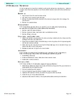
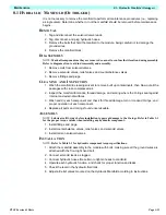
Check the hydraulic pressures whenever the pump, manifold, or relief valves have been ser-
viced or replaced.
M
AIN
R
ELIEF
V
ALVE
1. Operate the hydraulic system for 10-15 minutes to warm the oil.
2. Remove the cover from the 1st post.
3. Insert pressure gauge into high pressure gauge port marked ‘PT’ on top of front face of main
manifold block.
4. Loosen locknut on main relief valve and turn adjusting screw counter clockwise two full turns.
5. Operate telescope-in function switch at lower controls and keep it activated.
6. Slowly turn the main relief valve adjusting screw clockwise until the pressure gauge reads 155
Bar pressure.
7. Release Telescope-in switch.
8 Tighten locknut on main relief valve while holding the adjusting screw in position.
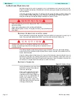
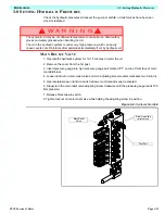
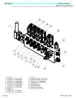
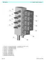
Figure 3-4:
Hydraulic Manifold
W A R N I N G
!
!
The hydraulic oil may be of sufficient temperature to cause burns. Wear safety
gloves and safety glasses when handling hot oil.
The oil in the hydraulic system is under very high pressure, which can easily
cause severe cuts. Obtain medical assistance immediately if cut by hydraulic oil.
Slew cross-line
relief valves
Main Relief
Valve
Test Port
Summary of Contents for TL38
Page 1: ...ERVICE PARTS MANUAL POWERED ACCESS WORK PLATFORM TL38 ...
Page 2: ......
Page 4: ......
Page 51: ...Page 3 28 Maintenance 3 17 Torque Specifications TL38 Service Parts NOTES ...
Page 59: ...Page 5 2 Schematics 5 1 Introduction TL38 Service Parts ...
Page 60: ...Page 5 3 Schematics 5 1 Introduction TL38 Service Parts ...
Page 61: ...Page 5 4 Schematics 5 1 Introduction TL38 Service Parts ...
Page 62: ...Page 5 5 Schematics 5 1 Introduction TL38 Service Parts ...
Page 63: ...Page 5 6 Schematics 5 1 Introduction TL38 Service Parts Notes ...
Page 66: ...Page 6 3 Illustrated Parts Breakdown General Assembly TL38 Service Parts ...
Page 70: ...Page 6 7 Illustrated Parts Breakdown Booms Posts Assembly TL38 Service Parts ...
Page 72: ...Page 6 9 Illustrated Parts Breakdown Platform Assembly TL38 Service Parts ...
Page 84: ...Page 6 21 Illustrated Parts Breakdown Outrigger Cylinder Assembly TL38 Service Parts NOTES ...
Page 86: ...Page 6 23 Illustrated Parts Breakdown Electrical Assembly TL38 Service Parts ...
Page 92: ...Page 6 29 Illustrated Parts Breakdown Decal Assembly TL38 Service Parts ...
Page 94: ...Page 6 31 Illustrated Parts Breakdown Decal Assembly TL38 Service Parts ...
Page 95: ...Page 6 32 Illustrated Parts Breakdown Decal Assembly TL38 Service Parts NOTES ...

