Page 3-13
Maintenance
3.9 - Hydraulic Manifold
TL38 Service & Parts
3.9 H
YDRAULIC
M
ANIFOLD
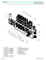
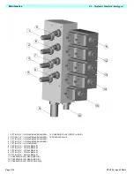
It is not necessary to remove the manifold to perform all maintenance procedures (i.e., replacing
a single valve). Determine whether or not the manifold should be removed before maintenance
begins.
R
EMOVAL
1. Tag and disconnect the solenoid valve leads.
2. Tag, disconnect, and plug hydraulic hoses.
3. Remove the bolts that hold the manifold to the module, being careful not to damage the
ground wires.
4. Remove the manifold block.
D
ISASSEMBLY
NOTE:
Mark all components as they are removed so as not to confuse their location during
assembly. Refer to diagram often to aid in disassembly and assembly.
1. Remove coils from solenoid valves.
2. Remove solenoid valves, relief valves and counterbalance valves.
3. Remove fittings and plugs.
C
LEANING
AND
I
NSPECTION
1. Wash the manifold in cleaning solvent to remove built up contaminants, then blow out all the
passages with clean compressed air.
2. Inspect the manifold for cracks, thread damage, and scoring where the O-rings seal against
internal and external surfaces.
3. Wash and dry each component and check for thread damage, torn or cracked O-rings, and
proper operation of each component.
4. Replace all parts and O-rings found unserviceable.
A
SSEMBLY
NOTE:
Lubricate all O-rings before installation to prevent damage to the O-rings. Refer to
Table 3-1 for the proper torque values when installing any hydraulic component.
1. Install fittings and plugs.
2. Install counterbalance valves, relief valves and solenoid valves.
3. Install coils on solenoid valves.
I
NSTALLATION
NOTE:
Refer to Table 3-1 for hydraulic component torque specifications.
1. Attach the manifold assembly to the module with bolts, making sure all the ground wires are
attached with the front right hand bolt.
2. Connect solenoid leads as tagged.
3. Connect hydraulic hoses. Be certain to tighten hoses to manifold.
4. Operate each hydraulic function, and check for proper function and leaks.
5. Check the level in the hydraulic fluid tank.
6. Adjust all relief valves mounted on the Hydraulic Manifold according to instructions.
Summary of Contents for TL38
Page 1: ...ERVICE PARTS MANUAL POWERED ACCESS WORK PLATFORM TL38 ...
Page 2: ......
Page 4: ......
Page 51: ...Page 3 28 Maintenance 3 17 Torque Specifications TL38 Service Parts NOTES ...
Page 59: ...Page 5 2 Schematics 5 1 Introduction TL38 Service Parts ...
Page 60: ...Page 5 3 Schematics 5 1 Introduction TL38 Service Parts ...
Page 61: ...Page 5 4 Schematics 5 1 Introduction TL38 Service Parts ...
Page 62: ...Page 5 5 Schematics 5 1 Introduction TL38 Service Parts ...
Page 63: ...Page 5 6 Schematics 5 1 Introduction TL38 Service Parts Notes ...
Page 66: ...Page 6 3 Illustrated Parts Breakdown General Assembly TL38 Service Parts ...
Page 70: ...Page 6 7 Illustrated Parts Breakdown Booms Posts Assembly TL38 Service Parts ...
Page 72: ...Page 6 9 Illustrated Parts Breakdown Platform Assembly TL38 Service Parts ...
Page 84: ...Page 6 21 Illustrated Parts Breakdown Outrigger Cylinder Assembly TL38 Service Parts NOTES ...
Page 86: ...Page 6 23 Illustrated Parts Breakdown Electrical Assembly TL38 Service Parts ...
Page 92: ...Page 6 29 Illustrated Parts Breakdown Decal Assembly TL38 Service Parts ...
Page 94: ...Page 6 31 Illustrated Parts Breakdown Decal Assembly TL38 Service Parts ...
Page 95: ...Page 6 32 Illustrated Parts Breakdown Decal Assembly TL38 Service Parts NOTES ...

