Page 3-17
Maintenance
3.10 - Hydraulic Pump
TL38 Service & Parts
3.10 H
YDRAULIC
P
UMP
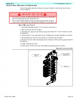
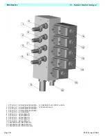
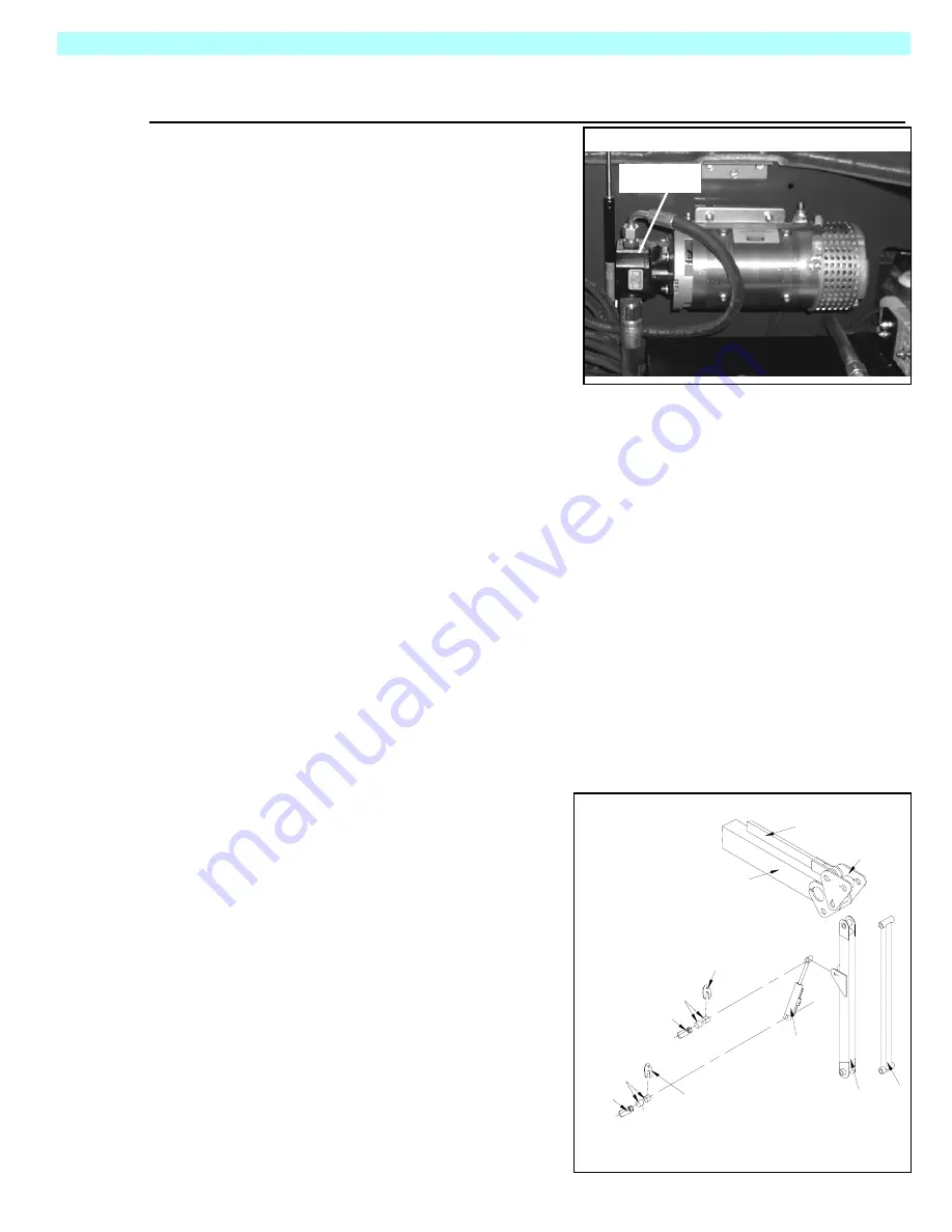
Figure 3-6:
Hydraulic Pump
R
EMOVAL
NOTE:
If the hydraulic tank has not been drained,
suitable means for plugging the hoses should be
provided to prevent excessive fluid loss.
1. Mark, disconnect, and plug the hose
assemblies.
2. Loosen the capscrews and remove the
pump assembly from the motor.
I
NSTALLATION
1. Lubricate the pump shaft with general pur-
pose grease and attach the pump to the
motor with the capscrews.
2. Using a criss-cross pattern torque each capscrew a little at a time until all of the capscrews
are torqued to 27 Nm (20 Ft/lbs).
3. Unplug and reconnect the hydraulic hoses.
4. Check the oil level in the hydraulic tank before operating the work platform.
3.11 H
YDRAULIC
C
YLINDER
(J
IB
)
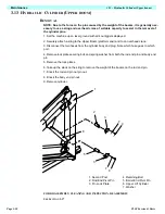
Note : Removal of the Jib cylinder requires the cage to be held in position by suitable sup-
port slings.
R
EMOVAL
1. Disconnect both hoses and plug ends to avoid excessive oil spillage. Note which hose goes to
which port.
2. Remove lock plate securing bolt and spring washer from both the rod end pin and body end
pin.
3. Remove lock plates.
4. Hold cage assembly in position and knock out rod end pin and body end pin.
5. Remove cylinder.
I
NSTALLATION
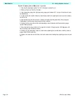
1. Lift the cylinder into place and insert the
body end pin in through the cylinder and boom.
Note: take care in aligning the pin in the
holes so that the pin can be pushed in by
hand. If the pin and holes are not properly
aligned and the pin is forced in, the bush-
ings will be damaged.
2. Line the holes up with the cylinder rod hole
and insert the rod end pin.
3. Slide both locking plates into the groves on
the pins and secure with the bolts and wash-
ers.
4. Test with weight at rated platform load to
check system operation.
PUMP
1
2
5
6
7
8
9
3
4
7
8
9
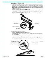
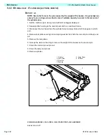
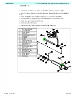
1. Levelling Rod
2. Upper Boom
3. Jib Link Weldment
4. Jib Weldment
5. Jib Tie Bar
6. Jib Cylinder
7. Pin Lock Plate
8. Bushings
9. Pins
Summary of Contents for TL38
Page 1: ...ERVICE PARTS MANUAL POWERED ACCESS WORK PLATFORM TL38 ...
Page 2: ......
Page 4: ......
Page 51: ...Page 3 28 Maintenance 3 17 Torque Specifications TL38 Service Parts NOTES ...
Page 59: ...Page 5 2 Schematics 5 1 Introduction TL38 Service Parts ...
Page 60: ...Page 5 3 Schematics 5 1 Introduction TL38 Service Parts ...
Page 61: ...Page 5 4 Schematics 5 1 Introduction TL38 Service Parts ...
Page 62: ...Page 5 5 Schematics 5 1 Introduction TL38 Service Parts ...
Page 63: ...Page 5 6 Schematics 5 1 Introduction TL38 Service Parts Notes ...
Page 66: ...Page 6 3 Illustrated Parts Breakdown General Assembly TL38 Service Parts ...
Page 70: ...Page 6 7 Illustrated Parts Breakdown Booms Posts Assembly TL38 Service Parts ...
Page 72: ...Page 6 9 Illustrated Parts Breakdown Platform Assembly TL38 Service Parts ...
Page 84: ...Page 6 21 Illustrated Parts Breakdown Outrigger Cylinder Assembly TL38 Service Parts NOTES ...
Page 86: ...Page 6 23 Illustrated Parts Breakdown Electrical Assembly TL38 Service Parts ...
Page 92: ...Page 6 29 Illustrated Parts Breakdown Decal Assembly TL38 Service Parts ...
Page 94: ...Page 6 31 Illustrated Parts Breakdown Decal Assembly TL38 Service Parts ...
Page 95: ...Page 6 32 Illustrated Parts Breakdown Decal Assembly TL38 Service Parts NOTES ...

