Page 4-2
TL38 Service & Parts
4.2 - Troubleshooting
TL38 Service & Parts
4.2 T
ROUBLESHOOTING
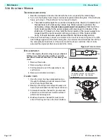
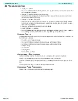
1. Verify your problem.
• Do a full function test from both the platform and chassis controls, and note all functions that
are not operating correctly.
2. Narrow the possible causes of the malfunction.
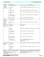
• Use the troubleshooting guide to determine which components are common to all circuits
that are not functioning correctly.
3. Identify the problem component.
• Test components that are common to all circuits that are not functioning correctly. Remem-
ber to check wires and terminals between suspect components. Be sure to check connec-
tions to battery negative.
4. Repair or replace any component found to be faulty.
5. Verify that repair is complete.
• Do a full function test from both the platform and chassis controls to verify that all functions
are operating correctly and that the machine is performing to specified values.
S
PECIAL
T
OOLS
Following is a list of tools which may be required to perform certain maintenance procedures on
the TL38 work platforms.
• Flow Meter with Pressure Gauge
• 0-69 bar (0-1000 psi ) Hydraulic Pressure Gauge with Adapter Fittings
• 0-207 bar (0-3000 psi) Hydraulic Pressure Gauge with Adapter Fittings
• Adapter Fitting
• Inclinometer
• Crimping Tool
• Terminal Removal Tool
A
DJUSTMENT
P
ROCEDURES
Hydraulic settings must be checked whenever a component is repaired or replaced.
Remove counterbalance valves and "bench test" them if they are suspect.
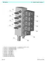
Connect a pressure gauge of appropriate range to the test port located on the hydraulic mani-
fold.
Correct pressure settings are listed in the hydraulic schematic.
C
HECKING
P
UMP
P
RESSURES
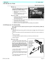
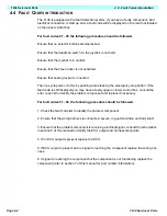
Remove hose from pump port and connect pressure gauge.
Summary of Contents for TL38
Page 1: ...ERVICE PARTS MANUAL POWERED ACCESS WORK PLATFORM TL38 ...
Page 2: ......
Page 4: ......
Page 51: ...Page 3 28 Maintenance 3 17 Torque Specifications TL38 Service Parts NOTES ...
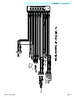
Page 59: ...Page 5 2 Schematics 5 1 Introduction TL38 Service Parts ...
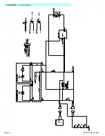
Page 60: ...Page 5 3 Schematics 5 1 Introduction TL38 Service Parts ...
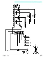
Page 61: ...Page 5 4 Schematics 5 1 Introduction TL38 Service Parts ...
Page 62: ...Page 5 5 Schematics 5 1 Introduction TL38 Service Parts ...
Page 63: ...Page 5 6 Schematics 5 1 Introduction TL38 Service Parts Notes ...
Page 66: ...Page 6 3 Illustrated Parts Breakdown General Assembly TL38 Service Parts ...
Page 70: ...Page 6 7 Illustrated Parts Breakdown Booms Posts Assembly TL38 Service Parts ...
Page 72: ...Page 6 9 Illustrated Parts Breakdown Platform Assembly TL38 Service Parts ...
Page 84: ...Page 6 21 Illustrated Parts Breakdown Outrigger Cylinder Assembly TL38 Service Parts NOTES ...
Page 86: ...Page 6 23 Illustrated Parts Breakdown Electrical Assembly TL38 Service Parts ...
Page 92: ...Page 6 29 Illustrated Parts Breakdown Decal Assembly TL38 Service Parts ...
Page 94: ...Page 6 31 Illustrated Parts Breakdown Decal Assembly TL38 Service Parts ...
Page 95: ...Page 6 32 Illustrated Parts Breakdown Decal Assembly TL38 Service Parts NOTES ...

