Page 5-2
Schematics
5.2 - Electric
Tm12 Work Platform - European
5.2 E
LECTRIC
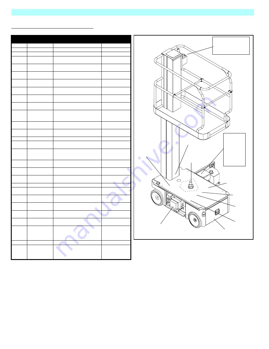
Legend:
Electric Schematic (107016-001)
DESIG-
NATION
NAME
FUNCTION
LOCATION
ALM
Alarm
Provides warning sound
Chassis Controls
BAT
Batteries
Provides power to work platform
Battery Tray
CHG
Battery Charger
Charges battery
Control Module
F1
5 AMP Circuit
Breaker
Electrical overload protection
Chassis Controls
F2
175 AMP Fuse
Overload protection for electric
motor
Control Module
HM
Hour Meter
Indicates hours of use and low
battery voltage.
Chassis Controls
I/O
I/O Board
Connection point for machine
function wiring
Control Module
MC
Motor Control
Controls the speed of electric
motor
Control Module
MOT
Motor
Provides power to hydraulic
pump
Control Module
R1
Motor Relay
Controls the speed of the electric
motor
Control Module
S1
Chassis
Emergency Stop
Switch
Shuts down all machine functions
Chassis Controls
S2
Chassis Lift
Switch
Elevates platform
Chassis Controls
S3
Chassis Key
Switch
Allows some machine functions
to be initiated from ground level
Chassis Controls
S4
Proximity Switch
Provides high speed cutout
Control Module
S5
Lift/Drive
Selector Switch
Activates lift or drive functions
Platform Controls
S6
Platform
Emergency Stop
Switch
Shuts down all machine functions Platform Controls
S7
Interlock Switch
Safety mechanism for PQ Control
Handle
Platform Controls
S8
PQ Control
Handle
Proportionally controls the drive
and lift functions
Platform Controls
S9
Platform Steering
Switch (2)
Control left and right steering
solenoids
Platform Controls
SNSR
Tilt Sensor
Activates tilt alarm
Control Module
SOL1
Steering Solenoid
(right)
Shifts steering valve to the left
Hydraulic Manifold
SOL2
Steering Solenoid
(left)
Shifts steering valve to the right
Hydraulic Manifold
SOL3
Platform Lift
Solenoid
Raises platform
Hydraulic Manifold
SOL4
Reverse Solenoid
Shifts forward/reverse valve to
reverse
Hydraulic Manifold
SOL5
Forward Solenoid
Shifts forward/reverse valve to
forward
Hyraulic Manifold
SOL6
Depression
Mechanism
Extension
Solenoid
Extends depression mechanism
bars
Hydraulic Manifold
SOL7
Down Solenoid
Lowers platform
Lift Cylinder
SOL8 &
SOL9
Depression
Mechanism
Retraction
Solenoid
Retracts depression mechanism
bars
Depression
Mechanism cylinder
S5 - S9
S1 - S3
F1
ALM
HM
SNSR
MC
F2
I/O
R1
CHG
MOT (behind charger)
Chassis
Upper Controller
Assembly
Controls
Control
Module
S4
Battery Tray
Summary of Contents for TM12
Page 1: ...TM12 ...
Page 10: ...Page VI Table of Contents List of Tables TM12 Work Platform European NOTES ...
Page 60: ...Page 3 34 Maintenance 3 18 Torque Specifications TM12 Work Platform European NOTES ...
Page 74: ...Page 5 6 Schematics 5 3 Hydraulic Tm12 Work Platform European NOTES ...
Page 79: ...Page 6 5 Illustrated Parts Breakdown TM12 Work Platform European NOTES ...
Page 81: ...Page 6 7 Illustrated Parts Breakdown Basic Assembly TM12 Work Platform European ...
Page 88: ...Page 6 14 Illustrated Parts Breakdown Hose Kit TM12 Work Platform European ...
Page 101: ......


