background image

System Function Inspection

114110-000 X-Series - Operator Manual

Page 5

S

YSTEM

 F

UNCTION

 I

NSPECTION

Refer to Figure 1 and Figure 2 for the locations of various controls and indicators.

W A R N I N G

!

!

STAND CLEAR

 of the machine while performing the following checks.

Before operating the machine, survey the work area for surface hazards such as holes, drop-offs, bumps, 
curbs, or debris.

LOOK up, down and around for overhead obstructions and electrical conductors.

Protect the control cable from possible damage while performing checks.

1. Move the machine, if necessary, to an unobstructed area to allow for full elevation.

2. Turn the Chassis and Platform Emergency Stop Switches ON by pulling the buttons out.

3. Turn and hold the Chassis Key Switch to CHASSIS. 

4. Push the Chassis Lift/Lower Switch to the LIFT position and elevate the platform approximately 

2,1 m (

7 ft.

).

5. Install the scissor brace as described on page 13.

6. Visually inspect the elevating assembly, lift cylinder, cables, and hoses for cracked welds and structural 

damage, loose hardware, hydraulic leaks, and loose wire connections. Check for missing or loose parts.

7. Verify that the Depression Mechanism Supports have rotated into position under the machine.

8. Check Level Sensor operation (see “Level Sensor” on page 14).

9. Remove the scissor brace as described on page 13.

10. Turn and hold the Chassis Key Switch to CHASSIS. 

11. Push the Chassis Lift/Lower Switch to the LIFT position and fully elevate the platform.

• Check for erratic operation.

12. Partially lower the platform by pushing Chassis Lift/Lower Switch to LOWER, and check for proper oper-

ation of the audible lowering alarm.

13. Check the Emergency Lowering Valve for proper operation (see “Emergency Lowering” on page 7).

14. Lower the platform.

15. Push the Chassis Emergency Stop Switch to check for proper operation. All machine functions should 

be disabled. Pull out the Chassis Emergency Stop Switch to resume.

16. Turn the Chassis Key Switch to DECK.

17. Check that the route is clear of surface hazards such as holes, drop-offs, bumps, curbs, or debris, and is 

level and capable of supporting the wheel loads.

18. Mount the platform and properly close and secure the entrance.

19. Turn the Lift/Drive Switch to DRIVE.

20. Check for speed and directional control.

• While engaging the Interlock Switch, slowly position the Control Handle to FORWARD then 

REVERSE. The farther you push or pull the Control Handle from center the faster the machine will 
travel.

X20W – X26N – X26UN – X31N: 

Perform this test in both HI and LOW DRIVE.

21. Push the Steering Switch RIGHT, then LEFT, to check for steering control.

22. Check clearances above, below, and to the sides of machine.

23. Turn the Lift/Drive Switch to LIFT to check platform lift controls. 

• While engaging the Interlock Switch, move the Control Handle to UP to raise the platform.

• While engaging the Interlock Switch, move the Control Handle to DOWN to lower the platform. The 

platform should descend and the audible lowering alarm should sound.

24. Push the Platform Emergency Stop Switch to check for proper operation. All machine functions should 

be disabled. Pull out the Platform Emergency Stop Switch to resume.

Summary of Contents for X20N

Page 1: ...sonnel shall carefully read understand and follow all safety rules operating instructions and the Scaffold Industry Association s MANUAL OF RESPONSIBILITIES of ANSI A92 6 1999 before performing maintenance on or operating any UpRight Aerial Work Platform P N 114110 000 ...

Page 2: ...trial Park Friel Avenue Nangor Road Dublin 12 Ireland TEL 353 1 620 9300 FAX 353 1 620 9301 FRONT REAR When contacting UpRight for service or parts information be sure to include the MODEL and SERIAL NUMBERS from the equipment nameplate Should the nameplate be missing the SERIAL NUMBER is also stamped on top of the chassis above the front axle pivot X Series Serial Number 20000 Current Stamped Ser...

Page 3: ...ated STOP carefully lower the platform Move the machine to a firm level surface IN CASE OF EMERGENCY push the Emergency Stop Switch to cut power to all machine functions NEVER perform service on the machine while the platform is elevated without blocking the elevating assembly NEVER recharge batteries near sparks or open flame batteries that are being charged emit explosive hydrogen gas NEVER repl...

Page 4: ...ing Procedure 9 Fold Down guardrails X31N 9 Fold Down Procedure 9 Erection Procedure 9 Parking Brake Release 10 Release the Parking Brake 10 Engage the Parking Brake 10 After Use Each Day 10 Transporting the Machine 11 Lifting By Crane 11 Moving By Forklift 11 Driving or Winching onto a Truck or Trailer 12 Maintenance 13 Blocking The Elevating Assembly 13 Scissor Brace Installation 13 Scissor Brac...

Page 5: ...L DESCRIPTION Figure 1 X 26 Ultra Narrow W A R N I N G DO NOT use the machine if all guardrails are not properly in place and secured 1 Platform Controls 2 Manual Case 3 Platform Extension 4 Platform 5 Elevating Assembly 6 Chassis 7 Power Module 8 Control Module 9 Chassis Controls 10 Batteries 11 Battery Charger 12 Charger Outlet Plug 13 Hydraulic Fluid Reservoir 14 Emergency Lowering Valve Knob X...

Page 6: ...red See Hydraulic Fluid on page 15 Add recommended hydraulic fluid if necessary See Specifications on page 20 3 Check that fluid level in the batteries is correct See Battery Maintenance on page 15 4 Verify that the batteries are charged 5 Check that the A C extension cord has been disconnected from the charger plug 6 Check that all guardrails are properly in place and secured 7 Inspect the machin...

Page 7: ... for erratic operation 12 Partially lower the platform by pushing Chassis Lift Lower Switch to LOWER and check for proper oper ation of the audible lowering alarm 13 Check the Emergency Lowering Valve for proper operation see Emergency Lowering on page 7 14 Lower the platform 15 Push the Chassis Emergency Stop Switch to check for proper operation All machine functions should be disabled Pull out t...

Page 8: ...le of supporting the wheel loads 3 Verify that the Chassis Key Switch is turned to DECK and the Chassis Emergency Stop Switch is ON pulled out 4 Mount the platform and properly close and secure the entrance 5 Check clearances above below and to the sides of machine 6 Pull the Platform Emergency Stop Switch out to the ON position 7 Turn the Lift Drive Switch to DRIVE NOTE Turn Lift Drive Switch to ...

Page 9: ...ired direction The speed of the machine will vary depending on how far from center the Control Han dle is moved 6 If the machine is not level the level sensor alarm will sound and the machine will not lift or drive If the level sensor alarm sounds the platform must be lowered and the machine moved to a firm level surface before attempting to elevate the platform LOWERING THE PLATFORM 1 Turn the Li...

Page 10: ...l could drop suddenly when the final retaining pin is retracted Keep hands away from the slide tubes to prevent injury c Push down on the platform extension guardrail to lower it completely The retaining pins will remain in the retracted position 4 Lower the side guardrails and rear guardrail as a single unit Repeat steps 3a through 3c 5 Lower the rear top rail Pull the two retaining pins and lowe...

Page 11: ...crews 4 Raise the side guardrails until the tops are level with the rear guardrail Install the set screws 5 Raise the slide out deck guardrail until the top is level with the side guardrails Install the set screws 6 Hang the controller on the slide out deck guardrail 7 Torque all set screws to 20 N m 15 ft lbs W A R N I N G DO NOT use the machine if all guardrails are not properly in place and sec...

Page 12: ...n increments to insure uniform adjustment and prevent binding 1 Chock the rear wheels to prevent the machine from rolling 2 Using a 13 mm socket wrench turn the brake release nuts clockwise until they contact the motor body 3 Alternately turn each nut clockwise in turn increments until resistance is felt approximately two turns 4 The brake is released ENGAGE THE PARKING BRAKE 1 Chock the rear whee...

Page 13: ...cure straps to chassis tie down lifting points only see Figure 7 MOVING BY FORKLIFT D A N G E R Forklifting is for transport only See specifications for the weight of the machine and be certain that the forklift is of adequate capacity to lift the machine Forklift from the rear of the machine using the forklift pockets provided If necessary the machine may be forklifted from the side by lifting un...

Page 14: ...ransport position b Set the wheels straight and turn off the machine c Chock the wheels B To Winch the machine onto the transport vehicle a Drive the machine up to the ramp b Attach the winch cable to the tie down lifting points c Release the parking brakes refer to Parking Brake Release on page 10 d Winch the machine into transport position e Chock the wheels f Re engage the parking brakes 2 Secu...

Page 15: ...below its attachment point 7 X31N From the left side of the machine pull the locking pin securing the brace Rotate the scissor brace counter clockwise until it is in the vertical position 8 Lower the platform by pushing the Chassis Lift Lower Switch to LOWER and gradually lower the platform until the scissor brace is supporting the platform SCISSOR BRACE STORAGE 1 Using the Chassis Controls gradua...

Page 16: ...he sensor is ON has power red indicates the sensor is LEVEL TESTING THE LEVEL SENSOR Figure 10 Level Sensor 1 Place machine on firm level surface 2 Use the Chassis Controls to raise the platform to approximately 2 1 m 7 ft 3 Install the scissor brace see Blocking The Elevating Assembly on page 13 4 Remove the Level Sensor electrical box cover near the front of machine 5 Push the Level Sensor off o...

Page 17: ...es when working near batteries Battery fluid is highly corrosive Thoroughly rinse away any spilled fluid with clean water Always replace batteries with UpRight batteries or manufacturer approved replacements weighing X20N X20W X26N 26 3 kg 58 lbs X26UN X31N 30 kg 66 lbs each Check the battery fluid level daily especially if the machine is being used in a warm dry climate If electrolyte level is lo...

Page 18: ...e minimum conductor diameter 15 m 50 ft maximum length to the charger plug located at the left side of the chassis Figure 13 Charge Indicator Lights 3 The charger turns on automatically after a short delay Look through the charge indicator cutout to check the state of charge 0 50 charge First Light BLINKING Second and Third Light OFF 50 75 Charge First Light ON Second Light BLINKING Third Light OF...

Page 19: ...VE MAINTENANCE CHECK LIST MAINTENANCE TABLE KEY Y Yes Acceptable N No Not Acceptable R Repaired Acceptable MAINTENANCE REPORT Date _______________________________________ Owner _____________________________________ Model No ___________________________________ Serial No ___________________________________ Serviced By _________________________________ COMPONENT INSPECTION OR SERVICES Y N R Battery C...

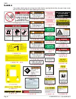
Page 20: ...BS OR 3 OCCUPANTS MAXIMUM SIDE LOAD 150 LBS WARNING 101250 004 MAXIMUM DISTRIBUTED PLATFORM LOAD 700 LBS OR 3 OCCUPANTS MAXIMUM SIDE LOAD 150 LBS WARNING 101250 005 FORK LIFT HERE FOR TRANSPORTING ONLY 014222 003 99 WARNING KEEP CLEAR OF SCISSORS BLOCK SCISSORS BEFORE SERVICING TIP OVER HAZARD DANGER Failure to read understand and obey the following safety rules will cause death or serious injury ...

Page 21: ...0 000 X Series Operator Manual Page 19 Figure 14 Safety Labels Locations X31N 6 26 20 2 11 7 14 15 10 12 20 2 21 25 17 4 3 3 18 22 23 24 19 9 1 16 16 25 13 5 25 9 7 7 8 REAR FRONT POWER MOUDLE CONTROL MODULE FRONT ...

Page 22: ... 2 35 m 92 5 in 2 35 m 92 5 in 2 35 m 92 5 in 2 35 m 92 5 in Overall Length Extension Out 3 26 m 128 5 in 3 26 m 128 5 in 3 26 m 128 5 in 3 26 m 128 5 in 3 26 m 128 5 in Drivable Height 6 1 m 20 ft 6 1 m 20 ft 7 9 m 26 ft 7 87 m 25 ft 10 in 9 4 m 30 ft 7 in Drive Speed Platform Lowered 0 to 3 2 km h 0 to 2 0 mph 0 to 3 2 km h 0 to 2 0 mph 0 to 3 2 km h 0 to 2 0 mph 0 to 3 2 km h 0 to 2 0 mph 0 to ...

Page 23: ...Call Toll Free in U S A 1 800 926 LIFT ...

Page 24: ...6184 Parts FAX 1 800 669 9884 801 South Pine Street Madera California 93637 http www upright com EUROPE TEL 353 1 620 9300 FAX 353 1 620 9301 Unit S1 Park West Industrial Park Friel Avenue Nangor Road Dublin 12 Ireland LOCAL DISTRIBUTOR P N 114110 000 09 02 ...

Reviews: