4. Gauges
■
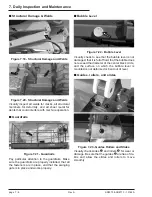
Water
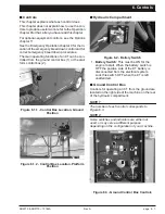
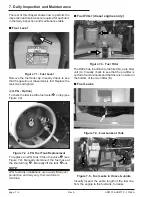
Figure 4.1 - Water Temperature Gauge
The wa ter gauge is lo cated on the ground con trol
box. It shows the tem perature of the wa ter-anti-
freeze mix ture in the en gine block. The typ ical op -
er at ing-tem per a ture range for Kubota en gines is
180°F to 205°F (82°C to 96°C), both die sel and
gasoline. (See the Au tomatic Shut-Offs & Cir cuit
Breakers chap ter 5 for more information.)
■
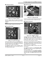
Amps
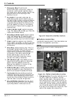
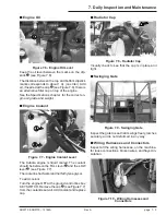
Figure 4.2 - Ammeter Gauge
The AMPS gauge shows the elec tric cur rent from
the al ternator to the bat tery. When the en gine is
running, the nee dle in the AMPS gauge should not
be to the left of 0. Un der nor mal op erating con di-
tions, af ter the en gine has been run ning for a few
minutes, the AMPS gauge should read 0.
■
Engine Oil
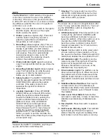
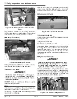
Engine oil level is mea sured with a dip stick. Oil ca -
pac i ties given in the Spec i fi ca tions chap ter 3 are
approximate. True val ues will vary from ma chine to
ma chine due to slight vari a tions or mod i fi ca tions
during production.
●
The oil dipstick is the only way to
accurately gauge if the engine oil level is
correct.
●
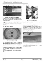
Engine oil level should always be between
the lines on the dipstick - never above the
top line or below the bottom line.
Gas o line
Die sel
Figure 4.3 - Oil Dipstick Levels for Gasoline
and Diesel Engines
■
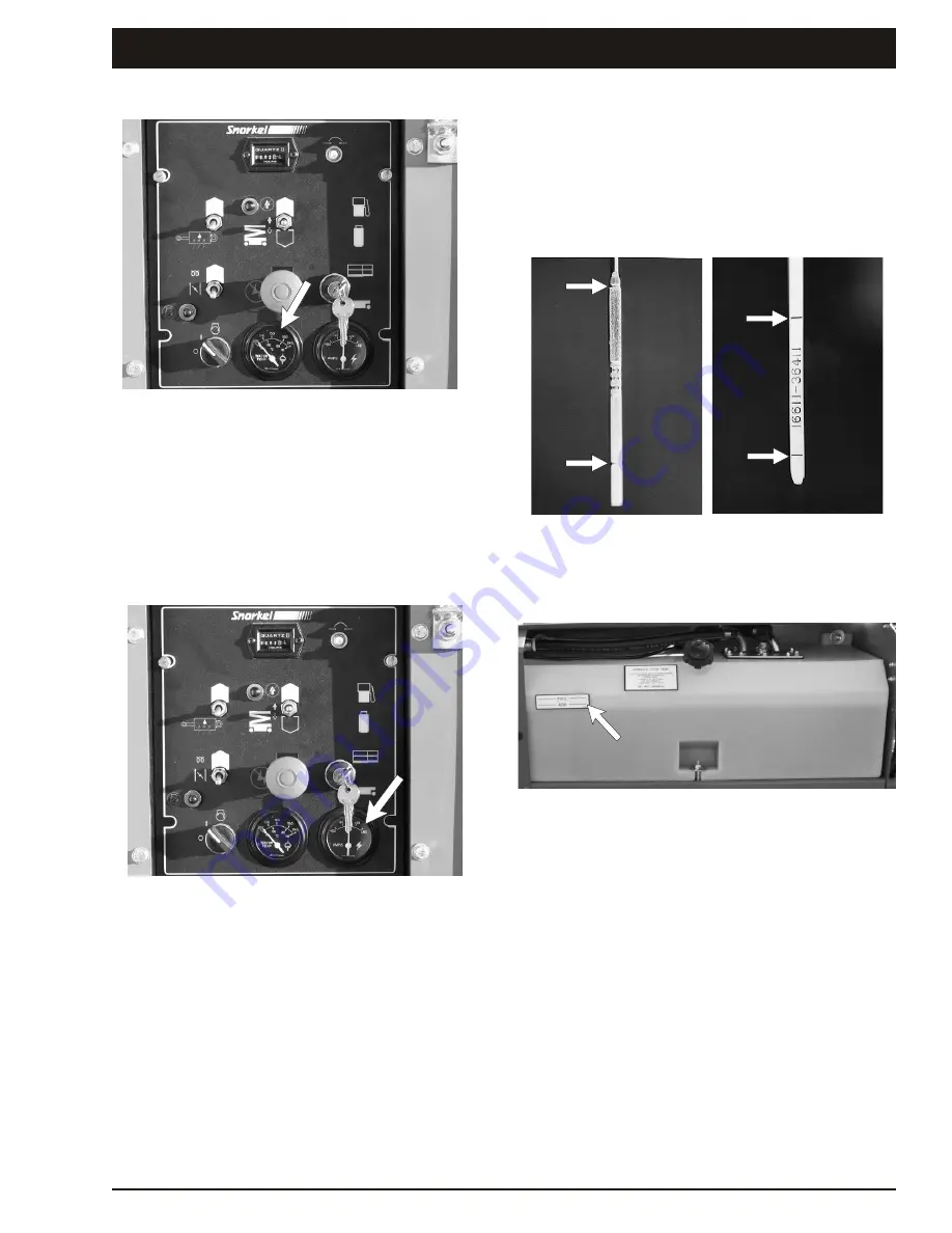
Hydraulic Oil Level
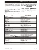
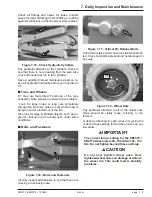
Figure 4.4 - Hydraulic Oil Level
The hy draulic-oil level gauge is on the side of the
hydraulic oil tank. It shows the ac tual level of oil in -
side the tank. Read it only when the plat form is
completely down. Oth erwise, the lift cyl inders be -
come large res ervoirs for hy draulic oil and the oil
level in the tank will be low. The oil level should be
within ( 0.25 inches, 6.4 mm) of the line.
SR3370 & SR2770 – 13184A
Rev A
page 4 - 1


