■
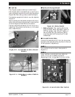
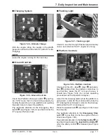
Charging System
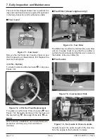
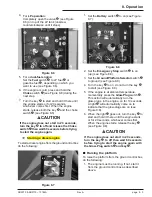
Figure 7.24 - Ammeter Gauge
With the en gine idling, the nee dle in the AMPS
gauge should not be to the left of 0" (left of 0" is dis -
charg ing).
NOTE
Leave the engine running for the next step
■
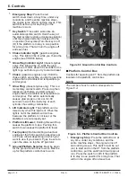
Ground Controls
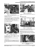
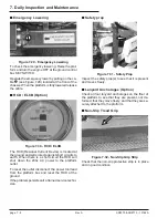
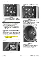
Figure 7.26 - Ground Controls
Check the Plat form Lift/Lower switch
(see Fig -
ure 7.26) to see that it is func tion ing prop erly by
hold ing the switch up to rise plat form and push ing
the switch down to lower the plat form.
Pay par tic u lar at ten tion to the Emer gency Stop
switch
(see Fig ure 7.26) to see that it turns the
RT
en gine off when struck.
■
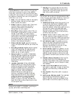
Flashing Light
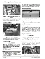
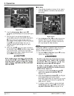
Figure 7.27 - Flashing Light
Check to see that the light flashes ap prox i mately
once a sec ond when the
RT
en gine is run ning.
■
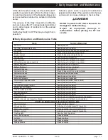
Platform Controls
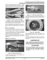
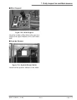
Figure 7.28 - Platform Controls
Check all of the lift •, drive
, steer
, and sta bi -
liser
func tions from the plat form con trol box to
see that they cause the
RT
to move the way it
should (see Fig
ure 7.28). (for cor
rect op
er
at
ing
pro ce dures see the Op er a tion chap ter ).
Lis ten for the low er ing alarm while the plat form is
go ing down. Lis ten for the mo tion alarm while the
RT
is be ing driven for ward. Lis ten for the back-up
alarm while the
RT
is back ing up.
Press the op er a tor horn
(see Fig ure 7.28) to see
that it works.
Pay par tic u lar at ten tion to the
Emer gency Stop
switch
to see that it turns the en gine off when
struck (see Fig ure 7.28).
Pay par tic u lar at ten tion to the
Safety Con trol
to
see that it de ac ti vates the
Joy stick Con trol ler
when the safety con trol
is re leased (see Fig ure
7.28).
SR3370 & SR2770 – 13184A
Rev A
page 7 - 7
7. Daily Inspection and Maintenance


