11. Options
This chap ter lists and ex plains the op tions avail -
able for an
RT
.
■
Bi-En ergy Option
This con sists of a com bi na tion of both a die sel en -
gine and a 24V DC mo tor to give a Bi-En ergy op -
tion.
Spe cif i cally, a 24V DC mo tor is mounted in the con -
trol cab i net. This pro vides an al ter na tive power
source to the die sel en gine.
The DC mo
tor is pow ered by four "Deep Cy cle
Trac tion Bat ter ies" and has an au to matic bat tery
charger that is mounted in the con trol cab i net.
❑
DC motor
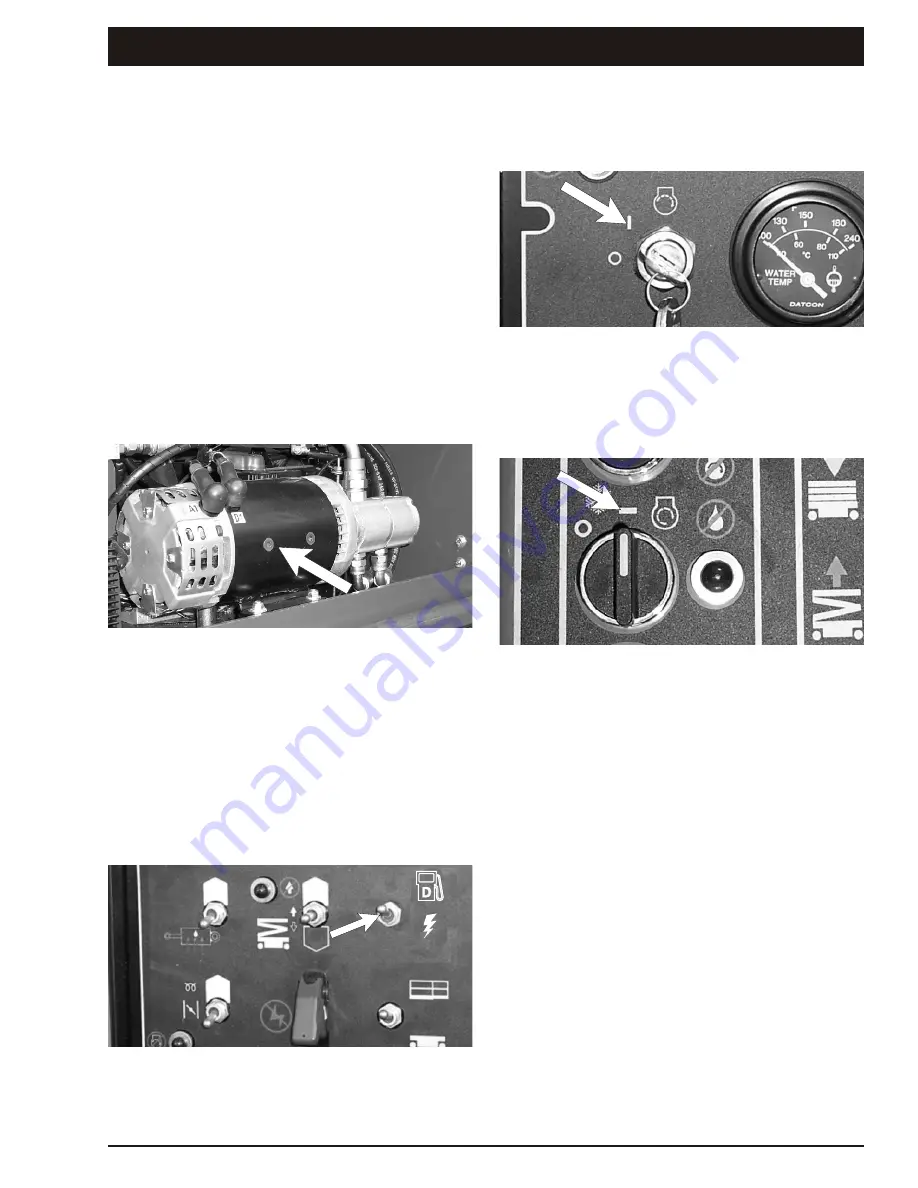
The DC mo tor lo cated in the con trol cab i net (see
Fig ure 11.1)
Figure 11.1 - DC Motor
❑
DC motor operation
A Die sel / Elec tric switch, on the lower con trol box
(see Fig ure 11.2) is used to se lect ei ther the die sel
en gine or the DC mo tor.
If the die sel en gine [
SWITCH UP
] is se lected the
DC mo
tor will not func tion and if the DC mo tor
(Elec tric) [
SWITCH DOWN
] is se lected the die sel
en gine will not run.
Figure 11.2 - Diesel/Electric Selection Switch
Af
ter se
lect
ing the DC mode, turn the ig
ni
tion
switch to the ON po si tion (the sec ond po si tion of
the switch) at the ground con trol box (see Fig ure
11.3)
Figure 11.3 - Start Switch, Ground
When en ter ing the plat form turn the ig ni tion switch
to the ON po
si
tion (the sec
ond po
si
tion of the
switch) at the plat
form con
trol box (see Fig
ure
11.4).
Figure 11.4 - Start Switch, Platform
Once the DC mode is se lected the mo tor will then
power all of the func tions in clud ing the sta bi lis ers in
the nor mal man ner. The only dif fer ence is that the
DC mo tor will only "run" when a func tion is se lected
e.g. rais ing the stack.
❑
Master battery isolater switches
There are two Mas
ter Bat
tery Iso
la
tor Switches
mounted at the end of the con trol cab i net (see Fig -
ure 11.5).
When the ma chine is not be ing used and is stowed
both of these bat tery iso la tor switches should be
turned to the "Off" po si tion.
When op er at ing with the
die sel mo tor
the 24V DC
bat tery iso la tor switch should be turned to the "Off"
po si tion.
When op er at ing the
24V DC mo tor
the Die sel bat -
tery iso la tor switch should be turned to the "Off" po -
si tion.
SR3370 & SR2770 – 13184A
Rev A
page 11 - 1


