Installation Manual
Troubleshooting
560-0405-00 Rev –
December 14, 2001
Page 49
© 2001 by UPS Aviation Technologies Inc.
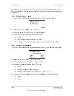
If internal failures are detected (causing the XPDR FAIL LED to illuminate), then the
cause of the failure will be displayed. Only one page will be displayed, with the three
most significant internal failures displayed.
a.
ICAO Address
b.
Internal component of Transponder
c.
Top Transmitter
d.
Bottom Transmitter
e.
Tx Synth Lock
f.
Rx Synth Lock
g.
Top Receiver
h.
Bottom Receiver
i.
Squitter Mon
9.2.3.8
Control Panel Fail Status
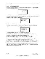
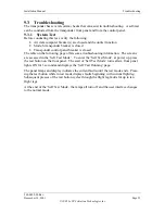
This display is used to display the failure status of the selected control panel input if a
failure is detected and the control panel fail LED is illuminated.
The first line is used to display which of the control panels is selected, either A or B. The
failure is displayed on the second line, either “Invalid”, “Rate Failed”, or “No Data”.
For flight leg results all three faults can be displayed one per line starting on the second
line. Both Control Panel A and B pages can be displayed if failures occurred on each
while they were selected.
Control Panel A
No Data


