232
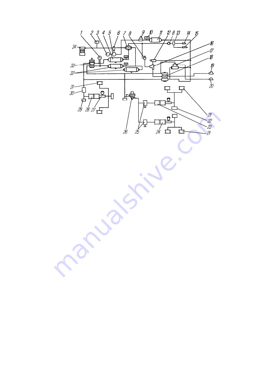
Fig. 136. Diagram of Service Brake Drive and
Trailer Brakes Double-Line Drive with Anti-Blocking System:
1 – two-pointer pressure gauge; 2 – tow valve; 3 – regenerating bottle*; 4 – air bottle
of front brake circuit; 5 – oil-water separator*; 6 – pressure regulator; 7 – triple safety
valve; 8 – trailer brake cut-off air valve; 9 – single safety valve; 10 – pressure drop
senders; 11 – air bottle of trailer brake circuit; 12 – trailer parking brake control valve; 13
– electropneumatic valve; 14 – fuel feed cut-off air cylinder; 15 – air cylinder for ex-
haust branch pipe flap closing; 16 – two-line valve; 17 – protection valve; 18 – control
valve for trailer brakes with double-line drive; 19, 20 – automatic coupling heads; 21 –
wheel brake cylinders of intermediate and rear axles; 22 – braking signal engagement
senders; 23, 24, 28 – brake pneumohydraulic boosters; 25, 30 – modulators; 26 – braking
forces regulator; 27 – brake failure sender; 29 – check outlet valves; 31 – front axle
wheel brake cylinder; 32 – air bottle of rear brake circuit; 33 – brake valve; 34 – com-
pressor
The electronic control unit
is the basic part of the anti-blocking system. The
control unit is located in the driver’s cab. The connecting diagram for plug-and-
socket joints of the control unit is shown in Fig. 137.
Auxiliary brake control.
The anti-blocking system is designed for supple-
mentary control of the auxiliary brake.
The control is performed by sending a signal from the electronic unit to the
electropneumatic valve, which breaks the air supply to the auxiliary brake cylinders,
letting the air out of them until the blocking stops.
After the blocking has stopped, the electropneumatic valve connects up the
auxiliary brake again until the driver disconnects it.
Wheel brake mechanism.
The front and rear brake mechanisms have coil
pickups 1 (Fig. 138). The wheel rotation is controlled with the help of pulse gear 3
moving in combination with the hub. The ring is pressed onto hub 4.
Coil pickup 1 comprises a permanent magnet with a round core and a coil.
Rotation of the pulse gear induces voltage impulses, the frequency of which is pro-
portional to the wheel speed. The sender is fastened to a special bushing. When
installing the sender, the adjustment of the air clearance is not required.
_____________________
* Except bolster trucks.


