54
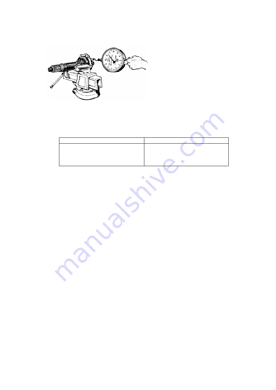
When using the dynamometer for measuring the torque, coil the cord on the spur
gear rim; the dynamometer readings should be as indicated in Table 3.
Table 3
Final drive ratio
Dynamometer readings, N (kgf)
6.7
7.32
8.05
8.9
16.5 - 27.6 (1.65 - 2.76)
17.6 - 29.3 (1.76 - 2.93)
18.8 - 31.3 (1.88 - 3.13)
20 – 33.4 (2.0 – 3.34)
Remember, that when shims are removed from under the body cap, when
adjusting the bearings, the driven bevel gear is shifted towards reduction of the
backlash; therefore, add shims under bearing body 5 to maintain the backlash.
3. Mount the body with the driving bevel gear into the final drive case. Torque
the body fastening bolts to 60-80 N.m (6-8 kgf.m). Check the correct meshing of the
bevel gears using the paint contact pattern. The pattern length should be 60 %,
minimum, of the tooth length (Tabl. 4).
The pattern should be offset by 5 mm, minimum, from the tooth narrow end,
the backlash (at the tooth root) being within 0.1-0.4 mm. For changing the backlash
in the bevel gears without disturbing the contact shift both gears to a distance,
which is proportional to the number of teeth of each gear, i.e. shift the driven bevel
gear 2.2 times (24:11) farther than the driving one.
4. Mount the differential and adjust the differential bearings. Tighten the
bolts fastening the differential bearing caps to 250-320 N m (25-32 kgf m). Adjust
the differential bearing using nuts 37 (see Fig. 39). Upon tightening the nuts the
distance between the differential bearing caps should increase by 0.04-0.14 mm.
When adjusting, turn the differential through for self
-
adjusting of rollers in the
bearings. The driven spur gear rim should be positioned symmetrically about the
driving gear rim.
Due to improved method of manufacturing the differential gears, the tooth
profile of half-axle gears and satellites has changed. The changed gears are not
interchangeable with the gears manuafctured before, and are to be replaced in set
only. To distinguish them, marks are introduced at the small module side, namely
a dia. 90 mm groove on the half-axle gear and a stepped end on the satellite.
When reassembling the final drive fit the inner ring and cage of roller bearing 2
of the driven bevel gear as shown in Fig. 39.
Fig.43. Checking Adjustment of
Driving Bevel Gear Bearings


