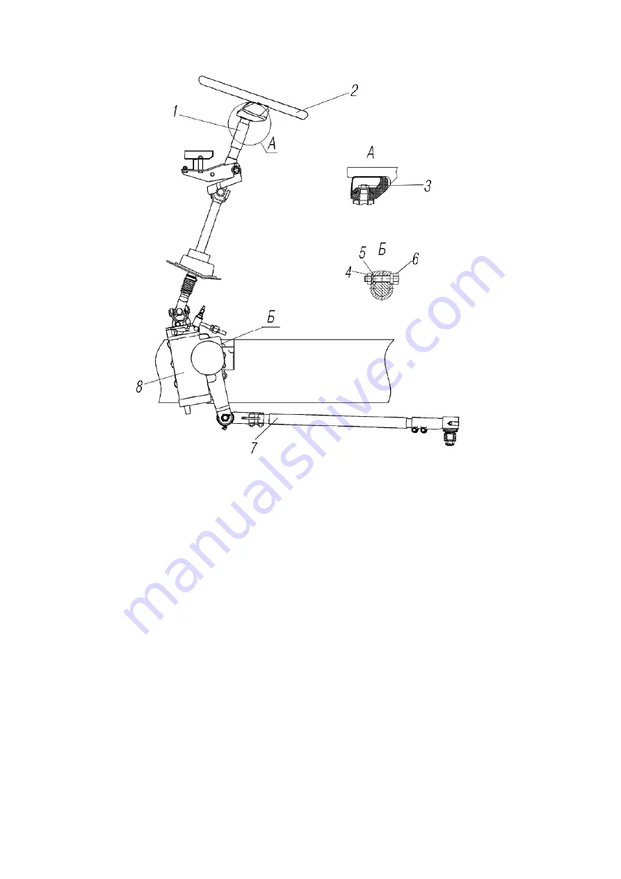
7-steering column; 2-steering wheel; 3,4-nuts; 5-washer; 6-bolt; 7-pull-rod of drop arm; 8-steer with arm
Figure 80 - Steering wheel of the cabover truck
4.4.2 Booster
4.4.2.1. Hydraulic circuit of the steering wheel (booster) is shown in figure 81.
4.4.2.2 Steer with the built hydraulic booster of the integral type.
Operational gear-
crew-ball nut-rod-sector. The rod is simultaneously the booster piston.
The axle gear wheel of the drop arm and the rod in the middle position does not have the
side clearance.
The device has the valve with the rotating spool, which consists of the operating in the
wormscrew 11 the rotating spool 1, as shown in figure 82. The rotating spool 1 and the worm-
screw head 11, located in the valve housing 12, have dosing grooves, located in radial directions.
103
Summary of Contents for 4320M
Page 1: ...URAL 4320М TRUCK and its Modifications ...
Page 106: ......
Page 110: ......
Page 159: ...156 Figure 123 Engine Electronic Control Unit Wiring Scheme ...
Page 165: ......
Page 167: ......
Page 173: ......
Page 177: ...Figure 140 Installation of left and right side safety devices 171 ...
Page 201: ......
Page 203: ......
Page 205: ......
Page 207: ......
Page 209: ......
Page 212: ......
Page 214: ......
Page 216: ......
Page 218: ......
Page 220: ......
Page 222: ......
Page 224: ......
Page 226: ......
Page 228: ......
Page 230: ......
Page 232: ......
Page 234: ......
Page 236: ......
Page 238: ......
Page 240: ......
Page 242: ......
Page 244: ......
Page 246: ......
Page 248: ......
Page 250: ......
Page 252: ......
Page 254: ......
Page 256: ......
Page 257: ...223 ...
Page 259: ......
Page 315: ...280 ...
Page 317: ......


