111
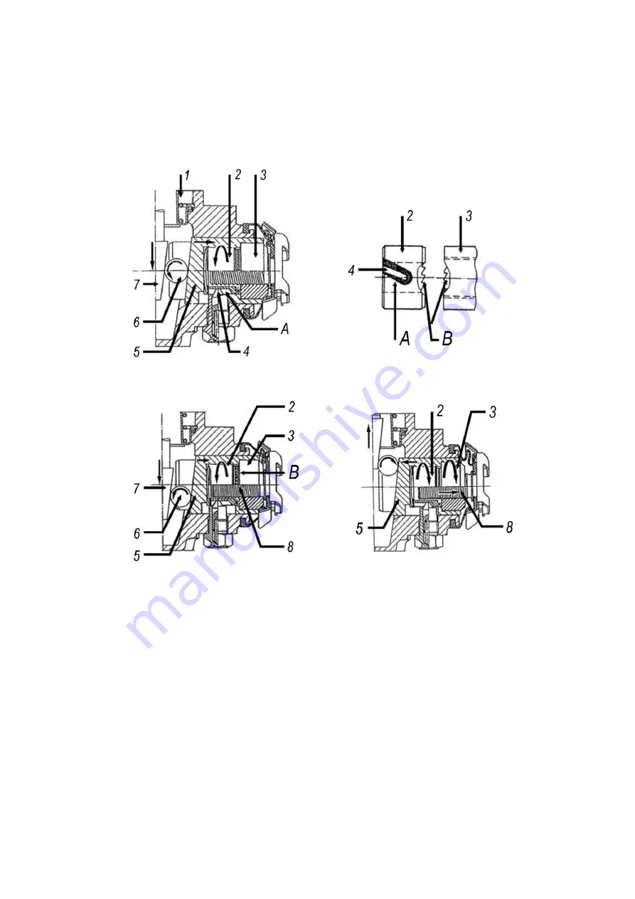
When releasing the brake the bolt 8, the adjusting nut 3, the gear ring 2 and the pistons 5
squeeze back inside. As the pin 4 bumps the helical groove “A”, the adjusting nut 3 and the gear
ring 2 turn for one tooth coupling pitch. The adjusting nut 3 moves the bolt 8 outside through the
thread, thus decreasing backlash appeared due to brake lining wear.
Through the tooth coupling “B” adjustment is made with very little speed - evenly with
the pitch of 0.03 mm.
I II
III IV
I-pinch;
II-tooth;
III-start of automatic adjustment;
IV-finish of automatic adjustment.
1-belleville spring; 2-gear ring; 3-adjusting nut; 4-pin; 5-pistons; 6-rollers; 7-cleat wedge; 8-adjusting bolt;
A-helical groove; B-tooth coupling
Figure 88 - Automatic Adjustment of the Pinch Clamp
Summary of Contents for 4320M
Page 1: ...URAL 4320М TRUCK and its Modifications ...
Page 106: ......
Page 110: ......
Page 159: ...156 Figure 123 Engine Electronic Control Unit Wiring Scheme ...
Page 165: ......
Page 167: ......
Page 173: ......
Page 177: ...Figure 140 Installation of left and right side safety devices 171 ...
Page 201: ......
Page 203: ......
Page 205: ......
Page 207: ......
Page 209: ......
Page 212: ......
Page 214: ......
Page 216: ......
Page 218: ......
Page 220: ......
Page 222: ......
Page 224: ......
Page 226: ......
Page 228: ......
Page 230: ......
Page 232: ......
Page 234: ......
Page 236: ......
Page 238: ......
Page 240: ......
Page 242: ......
Page 244: ......
Page 246: ......
Page 248: ......
Page 250: ......
Page 252: ......
Page 254: ......
Page 256: ......
Page 257: ...223 ...
Page 259: ......
Page 315: ...280 ...
Page 317: ......


