The lever 13 regulates fresh air intake in the cab. When the lever is in the right position,
the recirculation air flap is closed (air for heating is taken from the cab), in the left position the
recirculation air flap is opened (air is taken from outside).
The cab ventilation is realised through the ventipane, movable door windows and quarter
windows, and in summer season – through the heating system, when the heating unit tap is closed.
The independent air heating unit is installed on the cab floor, on the right side. Fuel feed-
ing is realised from the heating unit tank.
Upon operation of the independent heating unit, it is necessary to follow rules, specified in
the paragraph “Safety Requirements” and use the technical description and installation guidelines.
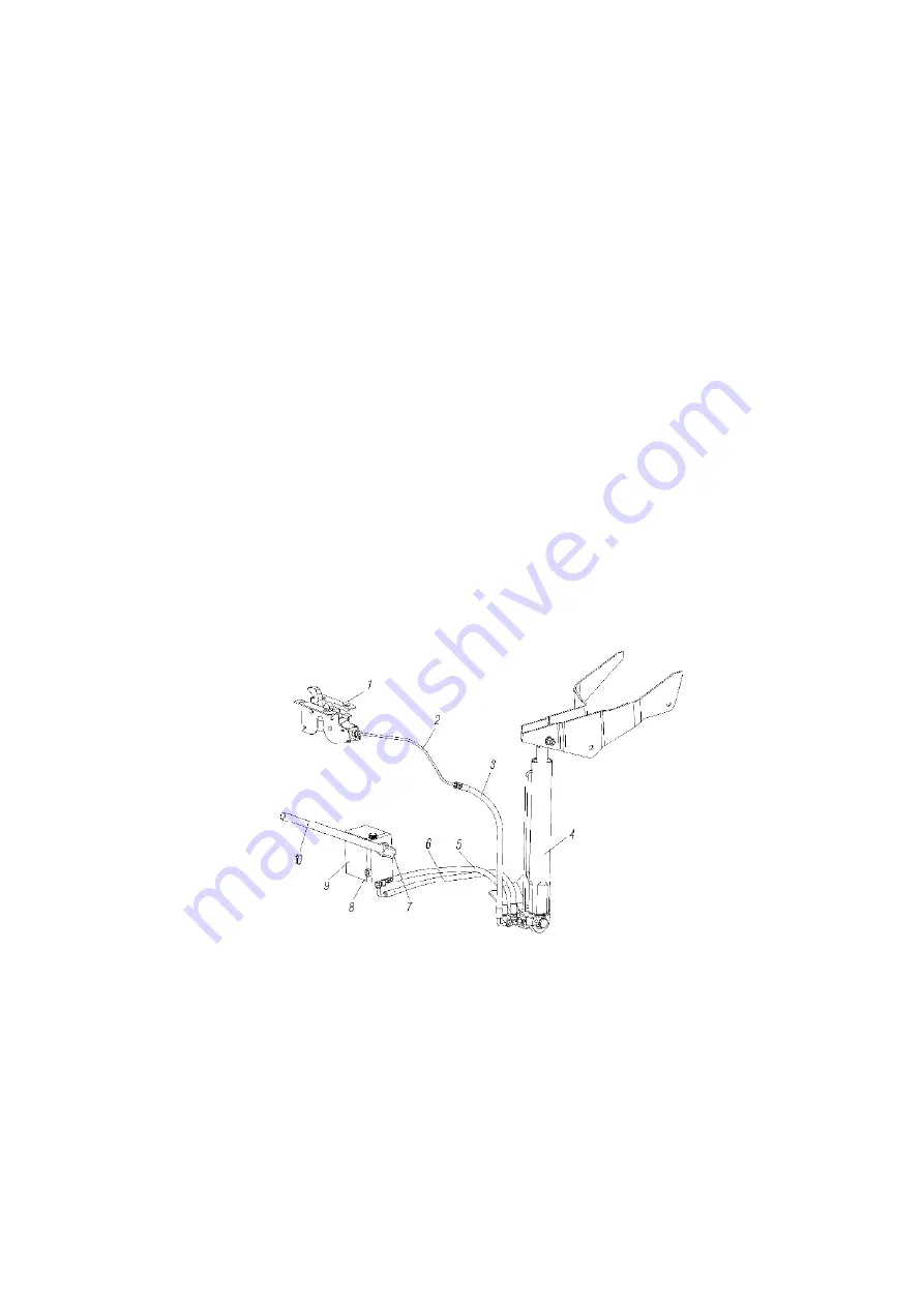
4.7.1.6 Hydraulic system of cabover truck roll over
is shown in figure 135 and in-
cludes the hydraulic pump 9, pipelines and high pressure hoses, the hydraulic cylinder of cab roll
over 4, the central lock of cab locking 1.
For the cab roll over it is necessary:
- turn clockwise the switch on the pump 8 by the lever 10, which is included in the tool
kit, against stop;
- put the lever in the sleeve bore of the pump 7 and, pumping it, raise the cab.
Opening of the central lock of cab locking happens automatically at the moment when
the cab starts raising.
To lower the cab down, it is necessary to turn the switch on the pump counter-clockwise
against stop, to put the lever in the sleeve bore of the pump and, pumping it, lower the cab. The
central lock latches automatically.
Caution! All possible operations below the cab shall be realized when the cab is
raised fully. Do not leave it in the intermediate position.
When the cab is not in the intermediate position, the engine starter blocks.
1-central lock of cab locking; 2-high-pressure pipeline; 3,5,6-high pressure hoses; 4-hydraulic cylinder of
cab roll over; 7-pump liner; 8-raise/lower switch; 9-hand-operated hydraulic pump; 10-lever
Figure 135
–
Hydraulic system of cabover truck roll over
167
Summary of Contents for 4320M
Page 1: ...URAL 4320М TRUCK and its Modifications ...
Page 106: ......
Page 110: ......
Page 159: ...156 Figure 123 Engine Electronic Control Unit Wiring Scheme ...
Page 165: ......
Page 167: ......
Page 173: ......
Page 177: ...Figure 140 Installation of left and right side safety devices 171 ...
Page 201: ......
Page 203: ......
Page 205: ......
Page 207: ......
Page 209: ......
Page 212: ......
Page 214: ......
Page 216: ......
Page 218: ......
Page 220: ......
Page 222: ......
Page 224: ......
Page 226: ......
Page 228: ......
Page 230: ......
Page 232: ......
Page 234: ......
Page 236: ......
Page 238: ......
Page 240: ......
Page 242: ......
Page 244: ......
Page 246: ......
Page 248: ......
Page 250: ......
Page 252: ......
Page 254: ......
Page 256: ......
Page 257: ...223 ...
Page 259: ......
Page 315: ...280 ...
Page 317: ......


