39
Central dimmer switch 30 (see figure 25) has three positions:
-on;
-sidelights, herein dashboard lighting is on;
-sidelights and dimlight.
To switch on or off the storage batteries push button 39.
Emergency alarm is switched on by pushing button 28, herein all direction indicators
and the lamp in the button start flashing.
The gearbox, transfer box, differential locks, power takeoff, additional power takeoff are
switched on according to the tables inside the cab and according to the instructions in paragraph
“Truck Driving”.
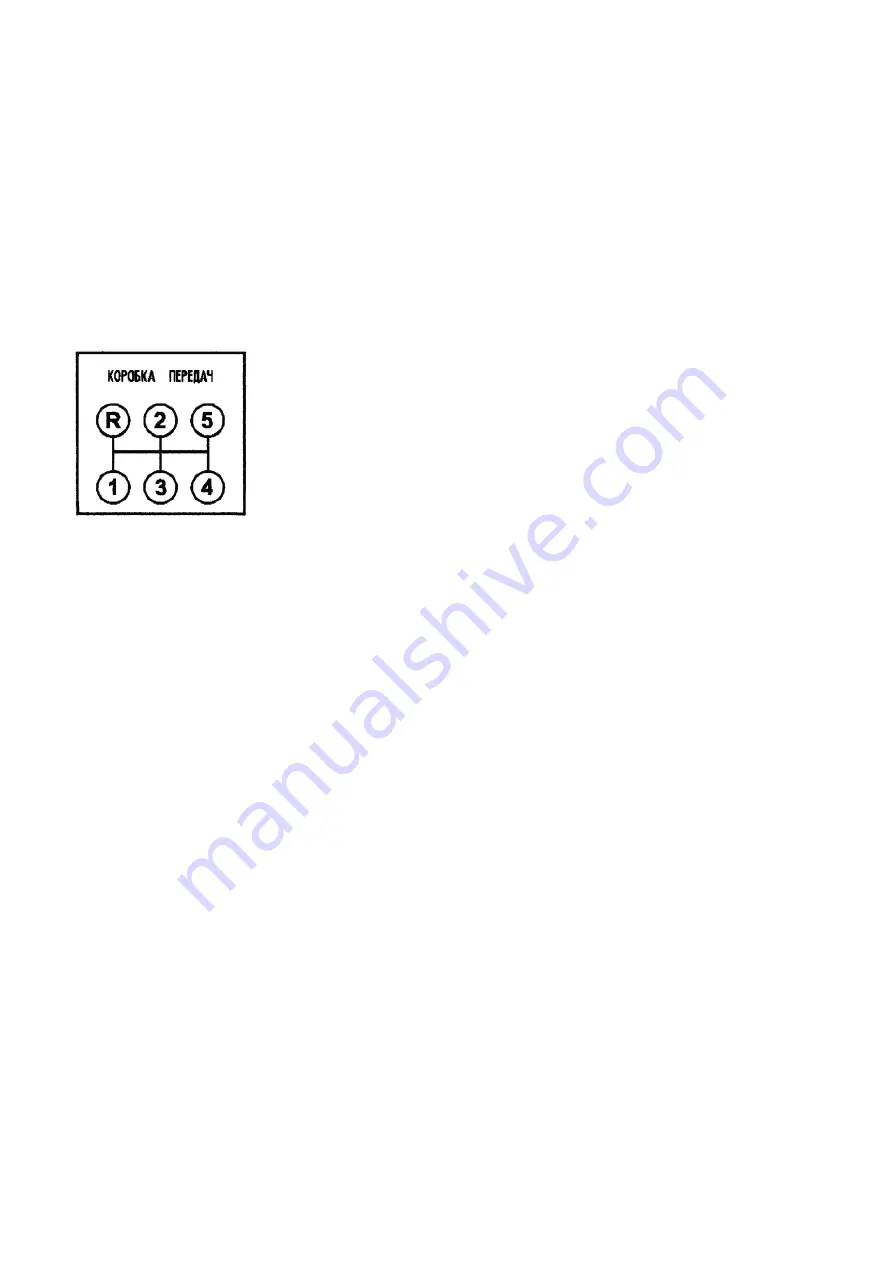
YAMZ 0905 gearbox shifting diagram is shown in figure 27.
Switch 22 switches on the interaxle differential lock of the transfer box (see figure 25) on
the control panel to the right from the driver. Transfer box gears are shifted as follows: with
switch 24 (has three detented positions: high gear, neutral, low gear) select the necessary gear,
press button 23 during 5...7 seconds and the selected gear is on. The gears are not shifted without
pushing button 23.
When turning the stator and tools key to the position I lamps 35 (interface block diag-
nostics indicator) and 38 (EDC) are flashing (see figure 25), herein the engine interface block and
engine diagnostics control are tested). When lamps 35 and 38 fade out, it means that block diag-
nostics is finished.
If lamp 35 is still flashing, it means that the engine interface block diagnostics has mal-
functions. To diagnose and eliminate the malfunction it is necessary to push switch 26 shortly and
read blind codes according to the Operation Manual for
“
Interface Engine Block
”
.
If lamp 38 is still flashing, it means that EDC has malfunctions. To diagnose and elimi-
nate the malfunction it is necessary to push switch 25 shortly and read blind codes according to
the Operation Manual for
“
YAMZ-53622-10, YAMZ-53642-10, YAMZ-53602-10 Engines
”
.
1-5-Gears; R-reverse
Figure 27 - Gear Shifting Diagram
for YAMZ-0905 Gearbox
Summary of Contents for 4320M
Page 1: ...URAL 4320М TRUCK and its Modifications ...
Page 106: ......
Page 110: ......
Page 159: ...156 Figure 123 Engine Electronic Control Unit Wiring Scheme ...
Page 165: ......
Page 167: ......
Page 173: ......
Page 177: ...Figure 140 Installation of left and right side safety devices 171 ...
Page 201: ......
Page 203: ......
Page 205: ......
Page 207: ......
Page 209: ......
Page 212: ......
Page 214: ......
Page 216: ......
Page 218: ......
Page 220: ......
Page 222: ......
Page 224: ......
Page 226: ......
Page 228: ......
Page 230: ......
Page 232: ......
Page 234: ......
Page 236: ......
Page 238: ......
Page 240: ......
Page 242: ......
Page 244: ......
Page 246: ......
Page 248: ......
Page 250: ......
Page 252: ......
Page 254: ......
Page 256: ......
Page 257: ...223 ...
Page 259: ......
Page 315: ...280 ...
Page 317: ......


