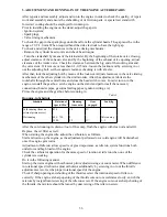
T
able 5
Maximum
T
olerated Limits of
W
ear
and Clearances Between Principal Mating Members of the Engine, mm
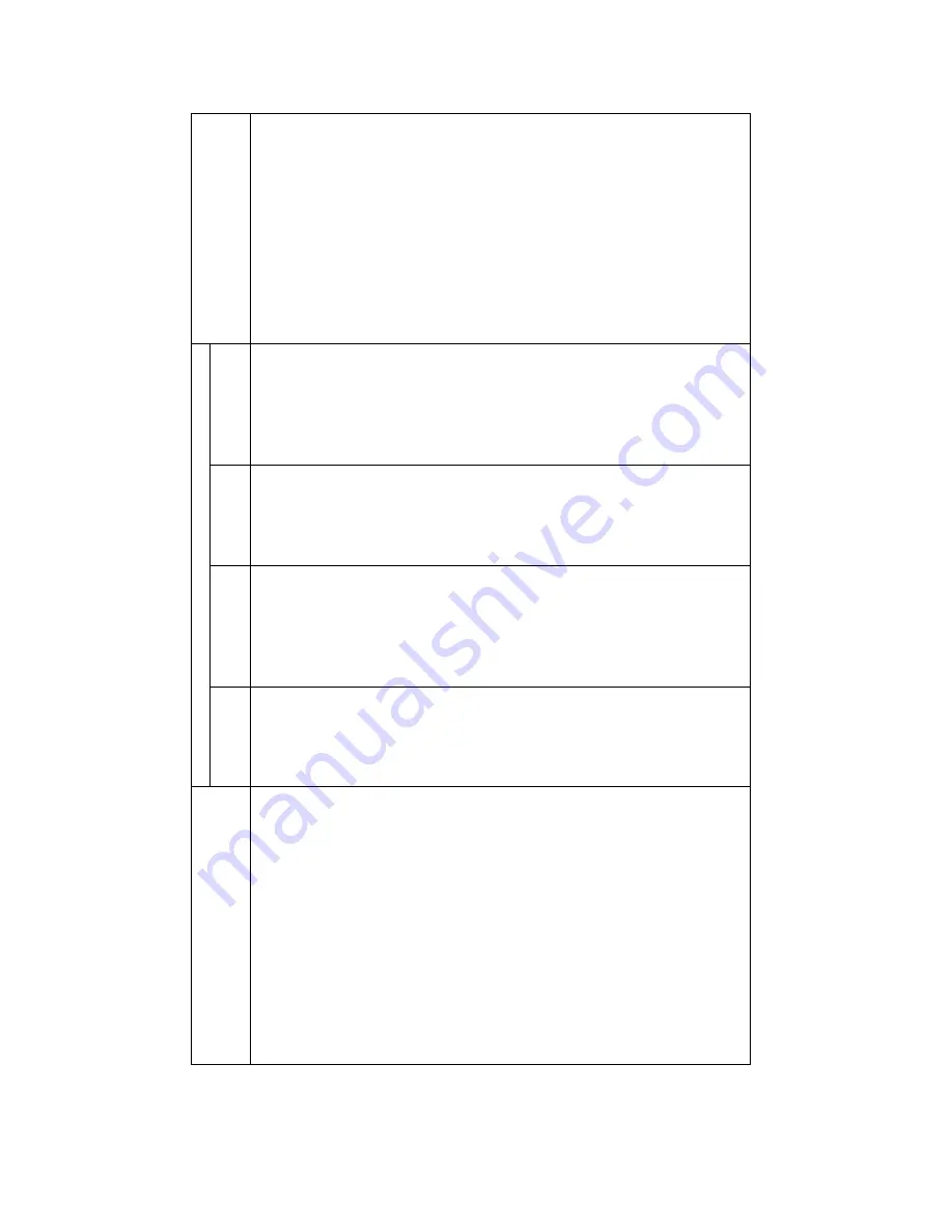
Maximum tolerances
Name of parts and mated pairs of parts
wear
on
diameter
out
-of
-r
ound and
taper
diameter
clearance
axial clearance
Measuring point and method
Crankpin to rol
le
rs to connecting rod big end
0.100
Crankpin
0.050
Connecting
- rod big end
0.050
Cylinder (face)
0.150
Out
-of
-round
0.070
In five po
ints (refer to
"Repairing the Crank Mechanism
”
of sub
section 2)
Cylin
der to piston
—
—
0.200
Measure piston
in plane, square to pin
axis at point
5
mm from the piston
lo
wer edge
Piston pin
0.015
Hole in piston to fit pin
0.020
Piston to piston pin
0.010
Connecting rod small end bush
0.02
5
Piston pin to connecting
rod small end bush
0.030
Compression ring (height)
0/050
Piston groove to piston ring
0.150
(by
depth)
'Piston groove to oil control ring
0.150
(by depth)
V
alve stem
0.120
V
alve guiding bush
0
.150
V
alve stem to
0.250
Guiding bush
0
.150
Rockshaft
0.070
Rocking arm
(aperture)
0.070
Rockshaft to rock
ing arm
0.120
T
appet
0.050
T
appet guide
0.050
T
appet to tappet
guide
0.100
45
Summary of Contents for 750cc Series
Page 1: ...Repair Manual 750cc All Models www imz ural com ...
Page 2: ......
Page 71: ...1 2 3 4 5 6 7 8 Fig 66 Final drive 71 ...
Page 98: ...Fig 11 iring Diagram 9 W 98 ...


