Repairing the Valve Timing Mechanism
The following troubles of the engine require repairs of the timing mechanism:
- Loss of compression in the cylinder due to leaky valves, followed by a drop in engine power,
increase in the gasoline consumption, and difficulties in starting the engine;
- Increased performance noises of the timing mechanism;
- When dismantling the engine, if any defects in the timing mechanism part are revealed.
Cylinder head.
Required tools and fixtures are:
- Tool 345-553 for removing valve springs;
- Indicator with stand;
- Inside caliper with 8 mm indicator
head
;
- Micrometer from 0 to 25 mm;
- Mandrel 345-047-3 for pressing in and out the valve guide bushing;
- Reamer 055-150-3, 8 mm dia., for reaming the valve guide bushing;
- Gauge 403-747 for checking straightness of hole in valve guide bushing;
- Puller with set of tools
345-326-3, 345-570-3 and 061-100-3 for forcing out the valve seat;
- Mandrel for pressing-in the valve seat;
- Tool 345-332-3 to rotate the valve while grinding;
- Set of cutters with mandrel 345-558, 032-106-6, 032-132 for machining the valve seats
chamfer.
Inspect all the accessible points in the cylinder head, make sure that there are no damage, cracks,
burns in the valves, stripped thread
s
; also check, whether the surfaces of the head-to-cylinder
fastening and that of the carburetor are level. In order to inspect the condition of valves, valve
guide springs, valve seats and to take the necessary measurements to determine wear, remove the
valves.
To remove the valves:
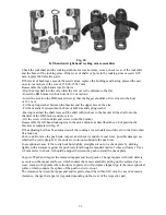
- Fasten the cylinder head on the tool 345-553, fit the lever on the stud securing the cylinder head
cover and secure the lever;
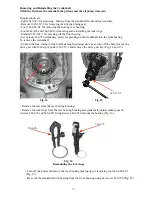
- Turning the lever, compress the valve springs
and remove the slide blocks (Fig. 40);
- Turn the lever round the stud and remove the side blocks from the other valve;
- Remove the top valve spring retainers, the springs and the valve spring seats;
- Free the cylinder head from the tool and remove the valves.
Clean thoroughly the removed parts of carbon, tar, etc., wash them and inspect.
While inspecting the valves, check:
- The clearance between the valve stem and the guide;
- Wear of the valve stem
- Condition of the valve head
seating chamfer.
While inspecting the cylinder
head, check:
- Wear of the guide bushing;
- Wear of the valve seat.
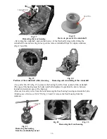
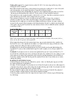
Check also resilience of the spring and its height in free state-Measure the side play between the
valve stem and the guide-bushing with the help of an indicator, the feeler pin of which should
rest against the valve stem end (Fig. 41) moved 4 mm out of the seat.
The clearance) should not exceed 0.25 mm (the indicator reads 0.32 mm). In case the clearance
exceeds the tolerated value, replace the valve (or both parts). For this purpose measure the dia-
meter of the valve stem and the guide bushing at a distance
of 5 mm from the upper and lower
edges of working surfaces. If the wear of the valve stem exceeds 0.12 mm, replace the valve if
the wear of the guide bushing exceeds 0.15 mm.
49
Summary of Contents for 750cc Series
Page 1: ...Repair Manual 750cc All Models www imz ural com ...
Page 2: ......
Page 71: ...1 2 3 4 5 6 7 8 Fig 66 Final drive 71 ...
Page 98: ...Fig 11 iring Diagram 9 W 98 ...

