Fig. 47.
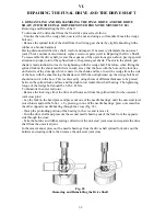
Removing the flexible coupling plate
1
2
Fig.46
Removing the Gear Shift Mechanism
The gearshift mechanism consists of the following assembly units and parts:
- Gear change foot pedal mechanism;
- Switch quadrant with a shaft;
- Reverse gear engagement mechanism with lever;
- Gearshift forks;
- Bracket with an intermediate gear.
Tool required are the crank handle 346-403 for turning the clutch shaft and 346-710 to remove
the flexible coupling plate.
To remove the gear shift mechanism:
- Unscrew the drain plug and drain oil out of the gear case;
- Remove the clutch release mechanism;
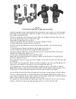
- Undo the nut of the kick-starter lever wedge, knock out the wedge with an aluminum hammer,
and remove the lever (Fig.46, Pos. 1);
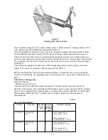
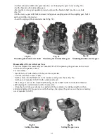
- Remove the flexible coupling plate (Fig.47);
- Turn off seven bolts fastening the gear case cover (Fig.46, Pos.2);
- Hammer slightly the clutch shaft end and the cover projections to force the shafts together with
the cover out of the gear case;
- Having unbent the lock washer undo the bolt fastening the reverse gear shift fork, remove the
fork;
- Take the axle and bracket with an intermediate gear out of the cover;
- Take the kick-starter shaft together with the gear out of the cover;
- Remove the forks shaft shafts.
- Press out the clutch and main shafts from the gear case cover by hammering slightly against
their end faces;
- Undo the bolts of right hand cover and force out the right-hand cover with the seal;
- Turn off the adjusting screws of the gear shift mechanism;
- Remove the lock ring of the quadrant shaft, shim and intermediate bushing.
- Remove the stop of the return spring;
- Remove the quadrant shaft and gear shift mechanism;
- Undo the nut and remove the reverse gear engagement lever from the axle;
- Remove the reverse gear engagement quadrant with a shaft and spring.
The mechanism thus removed should be washed and examined. If any damage or defects are
revealed, disassemble it, repair and reassemble.
59
Summary of Contents for 750cc Series
Page 1: ...Repair Manual 750cc All Models www imz ural com ...
Page 2: ......
Page 71: ...1 2 3 4 5 6 7 8 Fig 66 Final drive 71 ...
Page 98: ...Fig 11 iring Diagram 9 W 98 ...


